Supercharge Your Innovation With Domain-Expert AI Agents!

Electrokinetic fluidic system

a fluidic system and electrokinetic technology, applied in the direction of electrostatic separators, gas/liquid distribution and storage, electrostatic separation, etc., can solve the problems of affecting the mobility of liquid samples within the electrokinetic pump, hydrogen peroxide can disturb or destroy sensitive sample materials, e.g. proteins, to be studied, and the electrochemical reaction is undesirable, so as to eliminate the oxidation or reduction of electrolyte and eliminate the production

Active Publication Date: 2015-10-27
LUNAVATION AB
View PDF29 Cites 3 Cited by
  • Summary
  • Abstract
  • Description
  • Claims
  • Application Information

AI Technical Summary

Benefits of technology

This approach significantly reduces the production of unwanted by-products, maintains stable pH levels, and simplifies manufacturing, enabling efficient and reliable liquid flow control in microfluidic systems without harming sensitive biological samples.

Problems solved by technology

Such electrochemical reactions are undesirable.
Gases, when generated, can quickly break the electrical connection between the liquid sample, e.g. an aqueous sample, and the electrode, affecting the mobility of the liquid sample within the electrokinetic pump.
Further, generated acid, base and / or hydrogen peroxide can disturb or destroy the sensitive sample materials, e.g. proteins, to be studied.
The problem with today's electrokinetic pumps stems from the metal electrodes used to apply and maintain an electric field in the electrolyte.
These electrochemical processes often consume the electrolyte, e.g. water, itself, producing electrochemical by-products, such as H+, OH−, H2O2, H2 gas and O2 gas in the case of the electrolyte being water, which by-products can be detrimental to sensitive biological or chemical sample materials being transported or separated.
In the specific case of microfluidic devices, the production of H2 or O2 gas at a pump electrode can create a bubble which, eventually, blocks liquid from reaching the pump electrode and renders the microfluidic device useless.
Further, the formation of H+, OH− may change the pH of the electrolyte at the pump electrodes which may negatively affect the sample material to be studied.
Furthermore, the electrochemical reaction may cause consumption of, or otherwise disturb the environment of, the reagents or analyte used.
However, the external pump is often considerably larger than the LOC itself, and thereby precluding a self-contained device.
However, such internal mechanical pumps are often very expensive to manufacture.
Unfortunately, as previously described, internal electroosmotic pumps usually generate unwanted by-products in the electrolyte at the pump electrodes which impede their application in a LOC device or negatively impact the sample to be tested.
However, these chemicals can sometimes interfere with the materials being studied or transported, and are therefore undesirable.
Further, the use of a buffer implies an additional cost for manufacturing and operating the device.
However, this alternative is undesirable in microfluidic LOC devices due to the size of the large volume containers and due to the size requirements on LOC devices.
The challenge with this type of system is the sensitivity of biological samples and proteins to the Ag cation.
For example, a Ag cation is often toxic to bacteria or living cells.
Drawbacks with these types of electrokinetic pumps are that they are difficult to include in a miniaturized device as they often requires a larger footprint.
Furthermore, the complex geometries required and use of several different materials complicate their manufacture.
Further drawbacks are bubbles generated at the pumping electrodes, as well as changes in pH caused by hydrolysis.

Method used


Image

  • Electrokinetic fluidic system
  • Electrokinetic fluidic system
  • Electrokinetic fluidic system

Examples


example 1

Example of Electroosmotic Pump with PEDOT:PSS

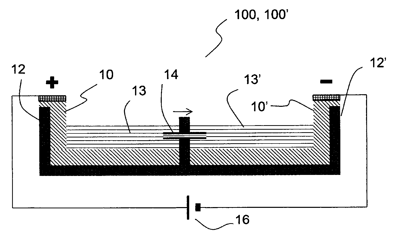
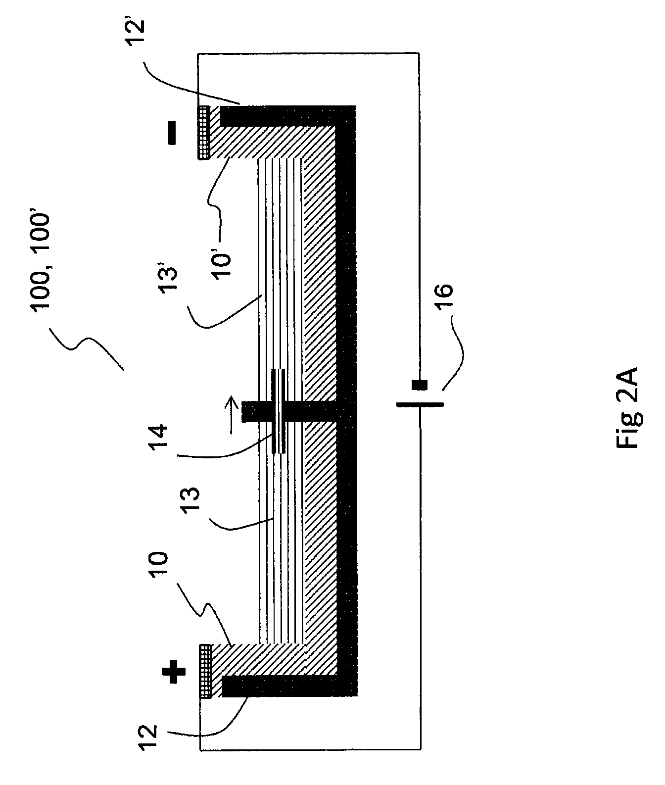
[0251]An exemplary electroosmotic pump has been manufactured by placing a capillary 14, e.g. a silica capillary, having an inner diameter between about 25 μm and about 75 μm, between two vessels 12, 12′ in a 128×86×12 mm (lwh) 8-well (each well is 40×30×12 mm) 2-3 cm-wide plastic dish. The pump occurs across the 30 mm wall. Each well contained a liquid electrolyte, 5-50 mM NaH2PO4 with pH 9. A PEDOT:PSS electrode 10, 10′ on a PET film was arranged in each vessel by submersing a portion of the PEDOT:PSS electrode in the electrolyte, and a potentials of up to 10V were applied between the electrodes by means of an electric field generator 16. Filling the two vessels 12, 12′ with salt solutions of different concentrations allowed the inventors to measure the flow rate through the capillary 14 indirectly via displacement without the use of additives, as the current transported through the capillary is proportional to the concentration of the e...

example 2

Further Exemplary Electroosmotic Pump

[0254]An electroosmotic pump comprising two vessels filled with an ionic solution, each vessel containing a PEDOT:PSS electrode and connected with a fused silica capillary functioning as a passageway between the vessels. One end of the electrode was submerged into the solution and the opposite end above surface connected to the electric field generator. The capillary was about 10 mm long and had an inner diameter in the range of about 25-75 μm. An electroosmotic flow was generated inside the capillary by applying a potential between the electrodes. The potential was selected to be in the range of about 1-100 V. Fluid movement was verified with a displacement setup where the two vessels had different ion concentrations, about 5 and about 22 mM of Na2HPO4, respectively, and the current through the capillary was monitored with a Keithley 2636A SourceMeter.

Results

[0255]For a 25 μm capillary the fluid displacement velocity was 20 μm / s for a potential ...

example 3

Operating the Electrodes at Low Voltage

[0258]In this example, an electrode such as those used in the system of Example 2 is shown to operate at low voltage. The electrode is a pi-conjugated polymer, namely PEDOT:PSS. Its performance, as the working electrode in a three-electrode configuration connected to a potentiostat (μAutolab by Metrohm) with a Ag / AgCl reference electrode and a Pt counter electrode, is compared to a similar experiment with a Pt electrode as the working electrode.

[0259]FIG. 6 shows the results in a cyclic voltammogram for platinum (Pt, dotted line) and PEDOT:PSS (solid line) electrodes in 20 mM NaCl(aq). Arrows show the oxidation and reduction peaks associates with PEDOT. It should be pointed out that the PEDOT:PSS electrode (solid line) always shows a current in this experiment, but the Pt-electrode shows almost no current when −0.8 V<E<1.2 V. E is the potential applied relative to the Ag / AgCl reference electrode.

[0260]The result in FIG. 6 demonstrates that, whe...


PUM

PropertyMeasurementUnit
diameteraaaaaaaaaa
pore sizeaaaaaaaaaa
inner diameteraaaaaaaaaa

Abstract

An electrokinetic fluidic system (100, 100′, 100″) for controlling liquid flow in e.g. a lab-on-a-chip system (200) comprising a first and a second electrode (10, 10′) said first and second electrode comprising a polymer based or oxide based conductive, electrochemically active electrode material, said electrode material being adapted to be subjected to an electrochemical reaction when in use in said electrokinetic fluid system (100).

Description

CROSS-REFERENCE TO RELATED APPLICATIONS[0001]This is a national stage application under 35 U.S.C. §371 of International Application PCT / SE2011 / 050199 filed Feb. 22, 2011. The present application claims priority from U.S. Provisional Application Ser. No. 61 / 306,586 filed on Feb. 22, 2010, and from Swedish Application No. 1050168-2 filed on Feb. 22, 2010. All of these applications are hereby incorporated herein by reference.TECHNICAL FIELD OF THE INVENTION[0002]The present invention relates to an electrokinetic fluidic system (100, 100′, 100″) for controlling liquid flow in e.g. a lab-on-a-chip system (200) comprising a first and a second electrode (10, 10′) and to an electrokinetic fluid system comprising such an electrode. The electrokinetic fluid system is configured to control liquid flow and / or particle flow in a microfluidic system for applications in biotechnology, analytical chemistry, etc.BACKGROUND OF THE INVENTION[0003]Microfluidic lab-on-a-chip (LOC) systems are stated to ...

Claims


Application Information

Patent Timeline
Patent Type & Authority Patents(United States)
IPC IPC(8): G01N27/453B01L3/00B03C5/02F04B19/00G01N27/447
CPCB01L3/50273B01L3/502707B03C5/02F04B19/006B03C2201/26G01N27/44791Y10T137/0391Y10T137/206B01L2300/0816B01L2300/161B01L2400/0418B01L2400/0424B01L3/5027
Inventor ROBINSON, NATHANIEL D.ERLANDSSON, PER
Owner LUNAVATION AB
Features
  • R&D
  • Intellectual Property
  • Life Sciences
  • Materials
  • Tech Scout
  • Unparalleled Data Quality
  • Higher Quality Content
  • 60% Fewer Hallucinations
Learn More