

PZT-based ferroelectric thin film and method of forming the same
a technology forming method, which is applied in the direction of stacked capacitors, fixed capacitor details, coatings, etc., can solve the problems of cracking in the formed film, deterioration of electrical properties or the like of ferroelectric thin film, and decrease in production efficiency, so as to achieve improved production efficiency, reduced crack generation, and dense structure
- Summary
- Abstract
- Description
- Claims
- Application Information
AI Technical Summary
Benefits of technology
Problems solved by technology
Method used
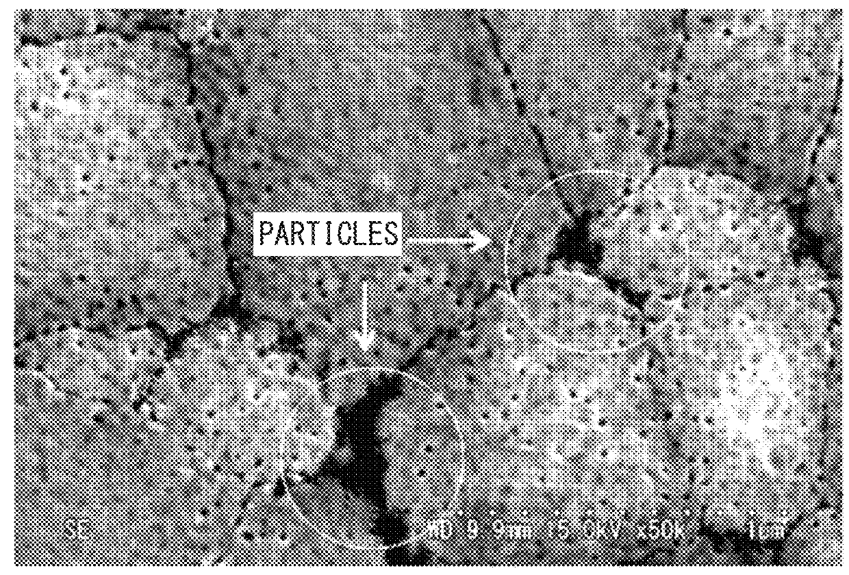
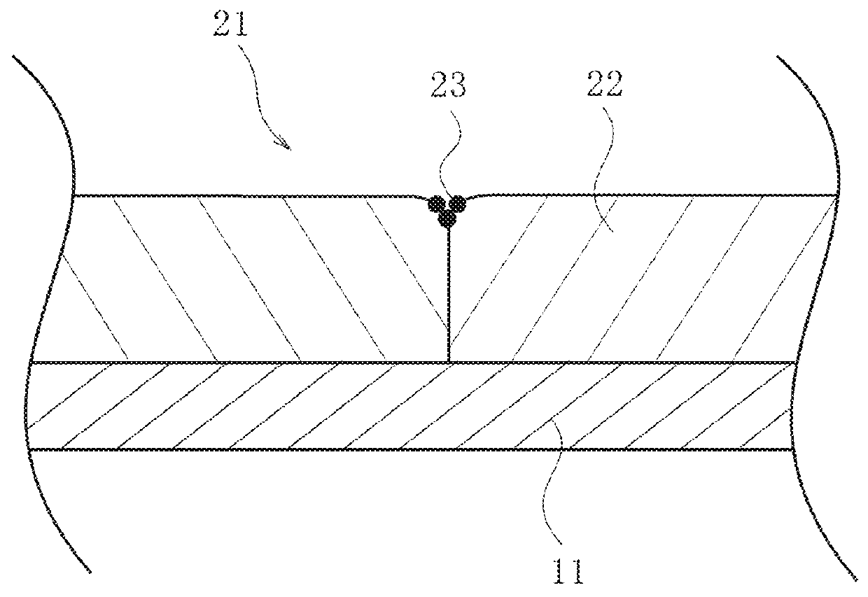
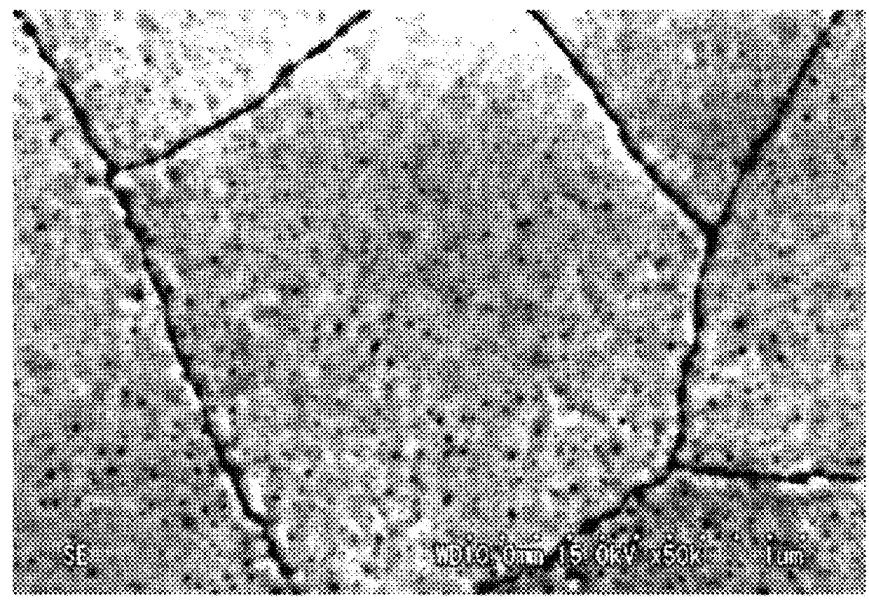
Image

Examples
example 1-1
[0065]First, as the PZT precursor, lead acetate trihydrate (Pb source), titanium tetraisopropoxide (Ti source), and zirconium tetrabutoxide (Zr source) were weighed such that a metal atomic ratio (Pb / Zr / Ti) was 115 / 52 / 48. These materials were added to propylene glycol in a reaction vessel. As a result, a synthetic solution was prepared. After the synthetic solution was re-fluxed in a nitrogen atmosphere at a temperature of 150° C. for 60 minutes, the solvent was removed from the synthetic solution by distillation. Next, acetyl acetone as the stabilizer was added to the synthetic solution.
[0066]Next, propylene glycol was added to the synthetic solution to dilute the synthetic solution such that the concentration of the PZT precursor was 35 wt % ire terms of oxides. Further, ethanol and N-methyl formamide were added to the synthetic solution to dilute the synthetic solution such that the concentration of the PZT precursor was 25 wt % in terms of oxides. Next, 0.30 enol of polyvinyl py...
examples 1-2 to 1-4
and Comparative Examples 1-1 and 1-2
[0070]PZT ferroelectric thin films were formed with the same method as that of Example 1-1, except that the ratio of the PZT precursor to the composition, the coating amount of the composition, or the amount of polyvinyl pyrrolidone added were changed as shown in Table 1 below.
examples 2-1 and 2-2
[0071]PZT ferroelectric thin films were formed with the same method as that of Example 1-1, except that the ratio of the PZT precursor to the composition, the coating amount of the composition or the number of coating processes thereof, and the amount of polyvinyl pyrrolidone added were changed as shown in Table 1 below. In Example 1-2, by repeating the processes from the formation of the coating film to pre-baking four times and performing baking once, a film having a desired total thickness was formed.
PUM
| Property | Measurement | Unit |
|---|---|---|
| particle size | aaaaa | aaaaa |
| particle size | aaaaa | aaaaa |
| thickness | aaaaa | aaaaa |
Abstract
Description
Claims
Application Information