Polyoxyalkylene polyol or monool and polyurethane resin

a polyol or monool and polyurethane technology, applied in the field of polyoxyalkylene polyol or monool, and a polyurethane resin, can solve the problems of insufficient reactivity of polyol, decrease in the number of functional groups, and mechanical properties deterioration, so as to achieve satisfactory mechanical properties and moisture resistance, satisfactory mechanical properties, and sufficient reactivity

Active Publication Date: 2016-07-12
SANYO CHEM IND LTD
View PDF21 Cites 20 Cited by
  • Summary
  • Abstract
  • Description
  • Claims
  • Application Information

AI Technical Summary

Benefits of technology

[0016]The polyoxyalkylene polyol or monool (S) of the present invention enables formation of a urethane resin having satisfactory mechanical properties and moisture resistance since the amount of a low molecular weight monool as a by-product is decreased and also it has sufficient reactivity as a raw material for the production of a polyurethane resin.
[0017]Also, the foamed or non-foamed polyurethane resin of the present invention has satisfactory mechanical properties and moisture resistance.

Problems solved by technology

This low molecular weight monool as a by-product has a problem that it causes a decrease in the number of functional groups of the polyoxyalkylene polyol and a urethane resin using such a polyol causes deterioration of mechanical properties.
Therefore, this polyol has insufficient reactivity as a polyol component of a thermosetting resin.
For example, this polyol has low reactivity with an isocyanate group of an isocyanate group-containing compound (tolylene diisocyanate, etc.) and has insufficient reactivity as a polyol component of a urethane resin.
However, since a polyethylene oxide moiety is hydrophilic, this method has a problem that hydrophobicity of the polyoxyalkylene polyol deteriorates and, when such a polyol is used, physical properties and the like of the urethane resin are largely changed by humidity.

Method used


Image

  • Polyoxyalkylene polyol or monool and polyurethane resin
  • Polyoxyalkylene polyol or monool and polyurethane resin
  • Polyoxyalkylene polyol or monool and polyurethane resin

Examples


example 1

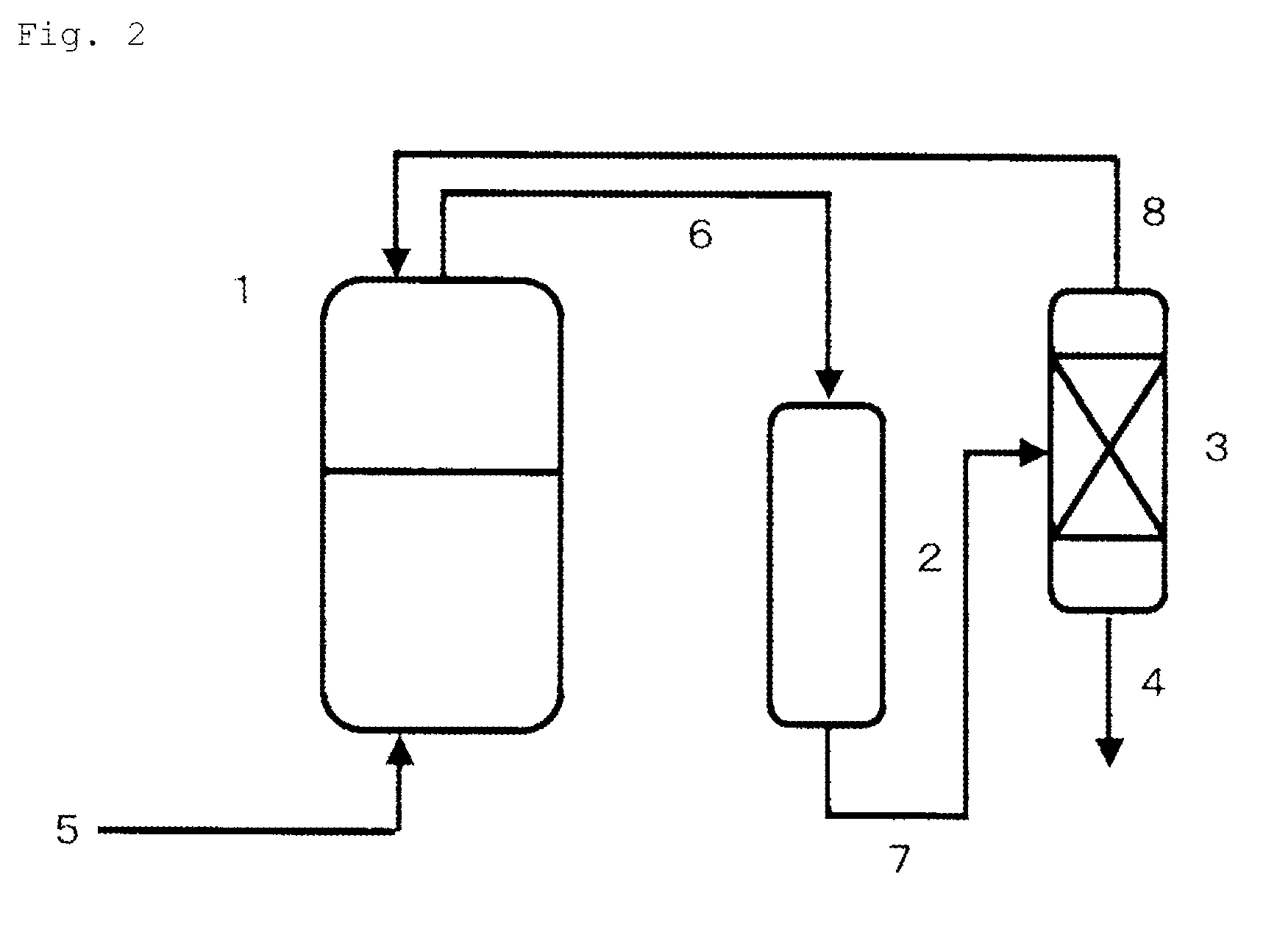
[0137]Like the aspect shown in FIG. 2, an autoclave made of stainless steel as a reaction vessel (1) (having a capacity of 2500 ml) equipped with a stirrer, a temperature control device and a raw material supply line (5) was connected to a reaction column (2) (using two cylindrical tubes made of stainless steel, each measuring 5.5 cm in inner diameter and 30 cm in length) filled with 400 parts of magnesium oxide (granules, diameter of 2 to 0.1 mm) and a distillation column (3) (theoretical plate number of 30, cylindrical tube made of stainless steel, 5.5 cm in inner diameter and 2 m in length) through circulation lines (6), (7), (8).

[0138]In the reaction vessel (1), 400 g of a PO adduct of glycerin (hydroxyl value of 280) and 0.09 g of tris(pentafluorophenyl) borane were charged, and then each pressure in the autoclave {reaction vessel (1)} and the reaction column (2), and the circulation lines (6), (7), (8) was reduced to 0.005 MPa. While continuously charging PO in a liquid phase ...

example 2

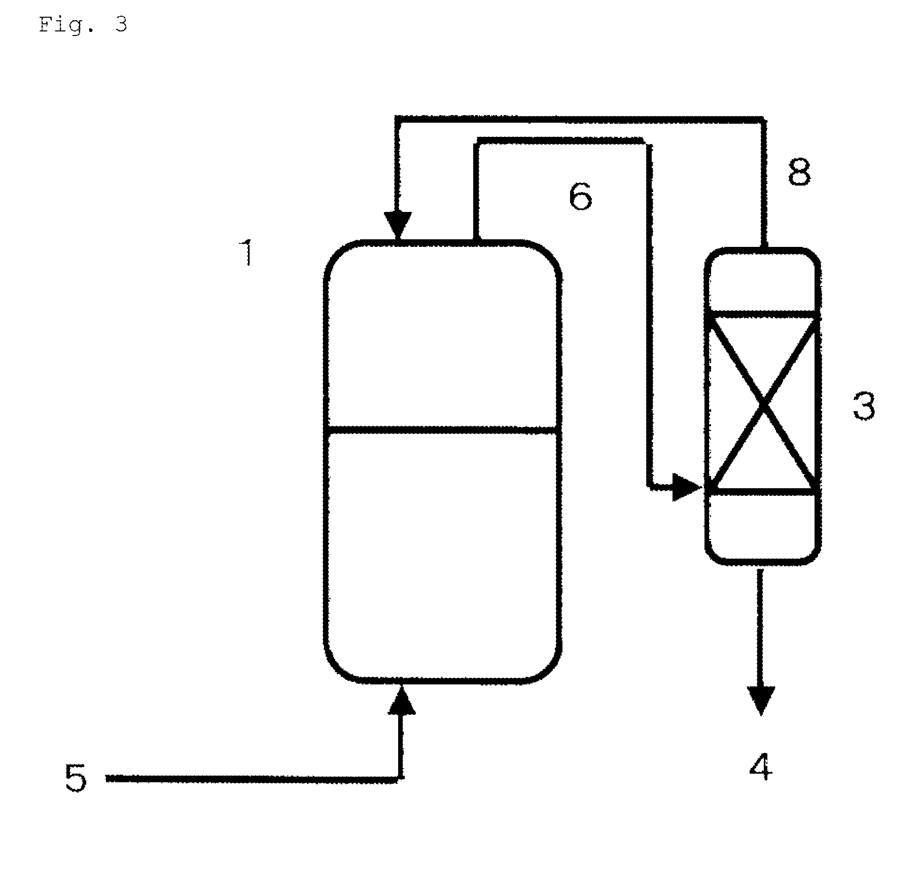
[0140]Like the aspect shown in FIG. 3, an autoclave made of stainless steel as a reaction vessel (1) (having a capacity of 2500 ml) equipped with a stirrer, a temperature control device and a raw material supply line (5) was connected to a distillation column (3) (theoretical plate number of 50, cylindrical tube made of stainless steel, 5.5 cm in inner diameter and 3 m in length) through circulation lines (6), (8).

[0141]In the reaction vessel (1), 400 g of a PO adduct of glycerin (hydroxyl value of 280) and 0.09 g of tris(pentafluorophenyl) borane were charged, and then each pressure in the autoclave {reaction vessel (1)} and the reaction column (2), and the circulation lines (6), (8) was reduced to 0.005 MPa. While continuously charging PO in a liquid phase through the raw material supply line (5) with controlling so as to maintain the reaction temperature at 50 to 60° C., a vapor phase in the reaction vessel (1) was circulated at a flow rate of 5 L / minute in the order of the react...

example 3

[0143]Like the aspect shown in FIG. 4, an autoclave made of stainless steel as a reaction vessel (1) (having a capacity of 2500 ml) equipped with a stirrer, a temperature control device and a raw material supply line (5) was connected to an adsorption column (9) (cylindrical tube made of stainless steel, 5.5 cm in inner diameter and 30 cm in length) filled with 500 parts of molecular sieve 4A through circulation lines (6), (8).

[0144]A PO adduct (400 g) of glycerin (hydroxyl value of 280) and 0.09 g of tris(pentafluorophenyl) borane were charged, and then each pressure in the autoclave {reaction vessel (1)} and the adsorption column (9), and the lines (6), (8) was reduced to 0.005 MPa. While continuously charging PO through the raw material supply line (5) with controlling so as to maintain the reaction temperature at 50 to 60° C., a vapor phase in the reaction vessel (1) was circulated at a flow rate of 5 L / minute in the order of the reaction vessel (1)→the vacuum line (6)→the adsor...


PUM

PropertyMeasurementUnit
hydroxyl valueaaaaaaaaaa
pressureaaaaaaaaaa
boiling pointaaaaaaaaaa

Abstract

There is provided a polyoxyalkylene polyol or monool (S) represented by formula (2). In the formula (2), R2 represents an m-valent group in which m active hydrogens are removed from the active hydrogen-containing compound (H); Z is an alkylene group or a cycloalkylene group, and these groups are unsubstituted or substituted with a halogen atom or an aryl group. A hydroxyl value x, total degree of unsaturation y and the content of ethylene oxide z satisfy mathematical expression (3). In mathematical expression (3), x represents 5 to 280 mgKOH / g, y represents total degree of unsaturation represented by a unit meq / g, and z is from 0 to 50.R2—[—(ZO)p-(AO)q-(CH2CH2O)r-H]  (2)y≦18.9×x−2×(100−z) / 100  (3)

Description

TECHNICAL FIELD[0001]The present invention relates to a polyoxyalkylene polyol or monool, and a polyurethane resin using the same.BACKGROUND ART[0002]Usually, a polyoxyalkylene polyol or monool is obtained by using an alkali metal such as potassium hydroxide as a catalyst, and performing addition polymerization of an active hydrogen-containing compound with an alkylene oxide such as propylene oxide or ethylene oxide. In the addition polymerization of PO using an alkali metal catalyst, a low molecular weight monool as a by-product is formed by transfer of PO to allyl alcohol. This low molecular weight monool as a by-product has a problem that it causes a decrease in the number of functional groups of the polyoxyalkylene polyol and a urethane resin using such a polyol causes deterioration of mechanical properties. Therefore, there is known a method of using cesium hydroxide or double metal cyanide as a catalyst in order to decrease the amount of such a low molecular weight monool as a...

Claims


Application Information

Patent Timeline
Patent Type & Authority Patents(United States)
IPC IPC(8): C08G18/48C08G18/08C08G18/28C08G65/26C08G18/50C08G18/40C08G18/66C08G101/00
CPCC08G18/4072C08G18/485C08G18/4825C08G18/4829C08G18/4854C08G18/4858C08G18/4866C08G18/4875C08G18/4879C08G18/5003C08G18/4845C08G18/14C08G18/283C08G18/6674C08G18/6688C08G65/2609C08G65/2654C08G65/2696C08G2101/005C08G2101/0008C08G2101/0083C08G2110/0008C08G2110/005C08G2110/0083C08G18/48C08G65/26C08L75/04
Inventor NAKAMINAMI, HIROMICHISUGAHARA, SHOGOYASUHARA, SHUMURATA, KOUICHI
Owner SANYO CHEM IND LTD
Why Eureka
Try Eureka