Breath analysis system, device and method employing nanoparticle-based sensor

a nanoparticle sensor and breath analysis technology, applied in the field of breath analysis systems, devices and methods for sensing analytes in fluids, can solve the problems of laborious, painful blood analysis, relatively expensive and often impractical, and the lack of well-explored breath chemistry

Active Publication Date: 2017-05-09
INVOY HLDG INC
View PDF2 Cites 33 Cited by
  • Summary
  • Abstract
  • Description
  • Claims
  • Application Information

AI Technical Summary

Benefits of technology

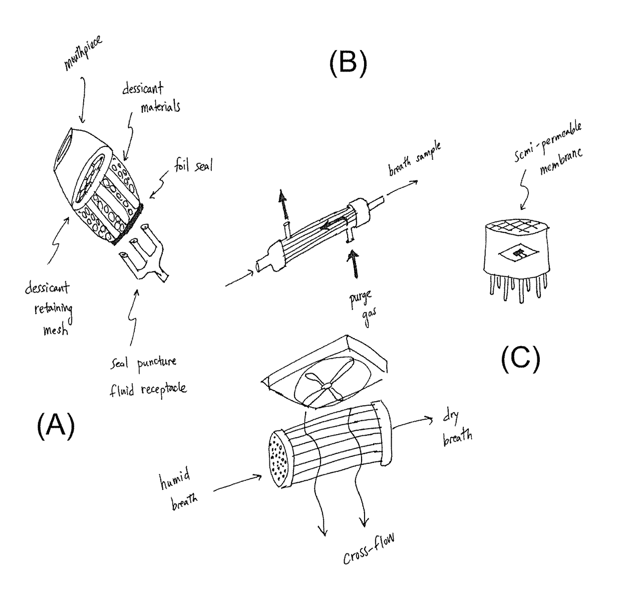
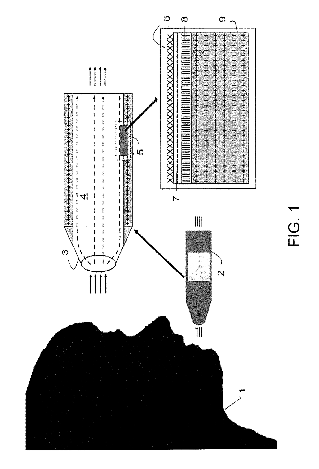
[0013]According to one aspect of the invention, the apparatus comprises a fluid collecting device configured to receive a sample of breath; a conditioning device coupled to the fluid collecting device and configured to receive the sample of breath and condition the sample with respect to at least one of temperature, flow rate, pressure, humidity, and concentration; and a sensing device coupled to the conditioning device and configured to receive the conditioned sample, wherein the sensing device includes a nanoparticle-based sensor and further whereby the analyte interacts with the sensing device to cause a change that is sensed by the sensing device and wherein the change comprises information useful in characterizing the analyte. Preferably, the apparatus is hand-held and characterizing the analyte is useful for health monitoring.
[0

Problems solved by technology

Historically, breath chemistry has not been very well exploited.
Blood analysis is painful, laborious, relatively expensive and often impractical due to lack of equipment or trained personnel.
While these companies have made home-testing possible, blood tests are still expensive and painful and they require careful disposal and procurement of employed equipment such as needles and collection vessels.
This leads to low patient compliance.
Urine analysis has been criticized as being inaccurate.
Thus, while blood and urine tests can provide information about the physiological state of an individual, they have been relatively unattractive or ineffective for practical application where portability or

Method used


Image

  • Breath analysis system, device and method employing nanoparticle-based sensor
  • Breath analysis system, device and method employing nanoparticle-based sensor
  • Breath analysis system, device and method employing nanoparticle-based sensor

Examples


example 1

[0386]FIG. 54 shows an embodiment that utilizes a pyroelectric detector 435. The analyte 437 passes through a conduit and interacts with an analyte interactant 432 which is immobilized on a test strip 431. The test strip 431 is passed through the conduit by a mechanism 434, such as a gear, motor, etc, and is guided by a strip director 433. The output of the pyroelectric detector 435 is processed by a signal processing unit 436.

[0387]As a general matter, the response of thermal sensors is improved by use of thin-film materials. In some instances, if the expected signal is large, the magnitude of the signal is perhaps not an issue. However, the thermal time constant (i.e. the response time) is typically impacted if the heat capacity is high. Accordingly, under most circumstances, it is desirable to employ thin-film materials. With this type of test strip embodiment, to ensure good thermal contact, it is desirable if the test strip is in good mechanical contact with the sensor.

[0388]A ...

example 2

[0394]In this example, a thermal sensor for oligosaccharide detection is described. Oligosaccharides (“glycans”) are associated with various pathologies, including cancer. These oligosaccharides may be found on the periphery of the cell on the glycocalyx. They also may be found free flowing in blood attached to biomolecules such as proteins. During disease states, the concentration of glycans may increase, the structure of the oligosaccharide may be modified or altered, or neoexpression of certain glycans may occur. Accordingly, measuring glycans can serve as tremendous biomarkers.

[0395]Although sugars are well-known as the “third language of life” (genomics, proteomics, glycomics), because glycoscience is an emerging field, it is important to understand why it is important to measure glycans. First, in some instances, glycans have served as biomarkers where other disease markers have not been identified or are limited (e.g. in multiple sclerosis). Second, many papers have shown tha...

example 3

[0413]FIG. 61 is a graph showing the sensitivity of an embodiment of a nanoparticle-based sensor to acetone. This embodiment comprised an Fe2O3 nanoparticle sensor. This sensor was tested in an environment with a continuous stream of gas (500 SCCM) mixed from compressed sources via mass flow controllers (to final percent volumes of 18% O2, 3% CO2, ppm levels of acetone, balance N2). Under dry, continuous gas streams, the sensitivity of the nanoparticle sensors to acetone is very high and stable.

[0414]FIG. 62 is a graph showing the sensitivity of an embodiment of a nanoparticle-based sensor to acetone. This embodiment comprised an Fe2O3 nanoparticle sensor. This sensor was tested with moderate amounts of humidity (20% RH at 37 deg C.) added to the continuously supplied simulated breath (18% O2, 3% CO2, ppm levels of acetone). The sensor response to even moderately high acetone concentrations (2 ppm in the figure) are severely impaired. The humidity chamber created a constant supply o...


PUM


Abstract

According to one aspect of the invention, the apparatus comprises a fluid collecting device configured to receive a sample of breath; a conditioning device coupled to the fluid collecting device and configured to receive the sample of breath and condition the sample with respect to at least one of temperature, flow rate, pressure, humidity, and concentration; and a sensing device coupled to the conditioning device and configured to receive the conditioned sample, wherein the sensing device includes a nanoparticle-based sensor and further whereby the analyte interacts with the sensing device to cause a change that is sensed by the sensing device and wherein the change comprises information useful in characterizing the analyte. Preferably, the apparatus is hand-held and characterizing the analyte is useful for health monitoring.

Description

[0001]This application claims the priority benefit of U.S. Provisional Application No. 61 / 315,884, filed Mar. 19, 2010. The entire contents of this application is hereby incorporated by reference and for which priority is claimed under 35 U.S.C. §120.BACKGROUND[0002]Field[0003]The invention relates generally to apparatus and methods for sensing analytes in a fluid, such as a liquid or a gas. A preferred example involves the sensing of one or more analytes in air or a gas expired by an individual for monitoring biochemical processes such as in diabetes, epilepsy, ovulation, weight loss, cholesterol biosynthesis, protein metabolism, and others occurring within that individual.[0004]Background[0005]There are many instances in which it is desirable to sense the presence and / or quantity of an analyte in a gas. “Analyte” as the term is used herein is used broadly to mean the chemical component or constituent that is sought to be sensed using devices and methods according to various aspect...

Claims


Application Information

Patent Timeline
IPC IPC(8): B01L3/00B01L9/00A61B5/097A61B5/083G01N33/98G01N33/497
CPCB01L9/54B01L3/5082G01N33/98B01L2300/0825A61B5/083B01L3/5085A61B5/097G01N33/4972B01L3/502A61B5/082A61B2010/0087A61B2560/0443A61B2562/0276A61B2562/0285A61B10/00B01L3/52B01L3/561C12Q1/25G01N33/542B01L2300/0663B01L2300/0832B01L2300/0896B01L2300/1877
Inventor AHMAD, LUBNA M.MARTINEAU, RHETT L.
Owner INVOY HLDG INC
Why Eureka
Try Eureka