
Systems and methods for selective auto-retroperfusion along with regional mild hypothermia

a technology of auto-retroperfusion and regional mild, applied in the field of system and method for selective auto-retroperfusion along with regional mild hypothermia, can solve the problems of increased risk of additional stroke(s), and increased mortality and morbidity rates, and achieve the effect of reducing the interior diameter

Active Publication Date: 2017-08-08
CVDEVICES
View PDF23 Cites 7 Cited by
  • Summary
  • Abstract
  • Description
  • Claims
  • Application Information

AI Technical Summary

Benefits of technology

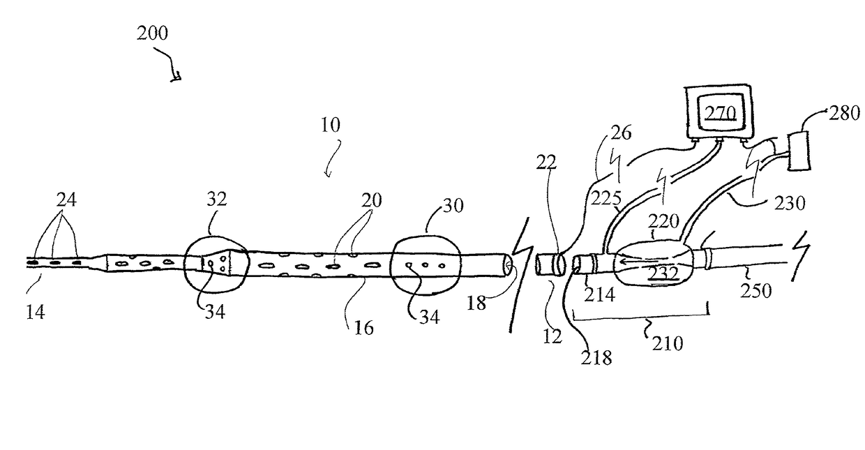
[0018]A flow unit for regulating the flow and pressure of a fluid is also described herein. The flow unit comprises an elongated body having an open proximal end, an open distal end, an interior extending between the open proximal end and the open distal end. The flow unit further comprises a chamber surrounding at least a portion of the elongated body. The chamber comprises an interior and at least one port in fluid communication with the interior of the chamber which is adapted to couple with a fluid source. The chamber of the flow unit is adapted to expand and deflate. In at least one embodiment, the section of the interior of the elongated body associated with the portion surrounded by the chamber comprises a first diameter when the chamber is deflated and a second diameter when the chamber is expanded. Here, the second diameter is less than the first diameter, such that the chamber reduces the size of the interior of the elongated body when the chamber is expanded. Further, the interior of the chamber may be adapted to exert a compressive force on the portion of the elongated body surrounded thereby.
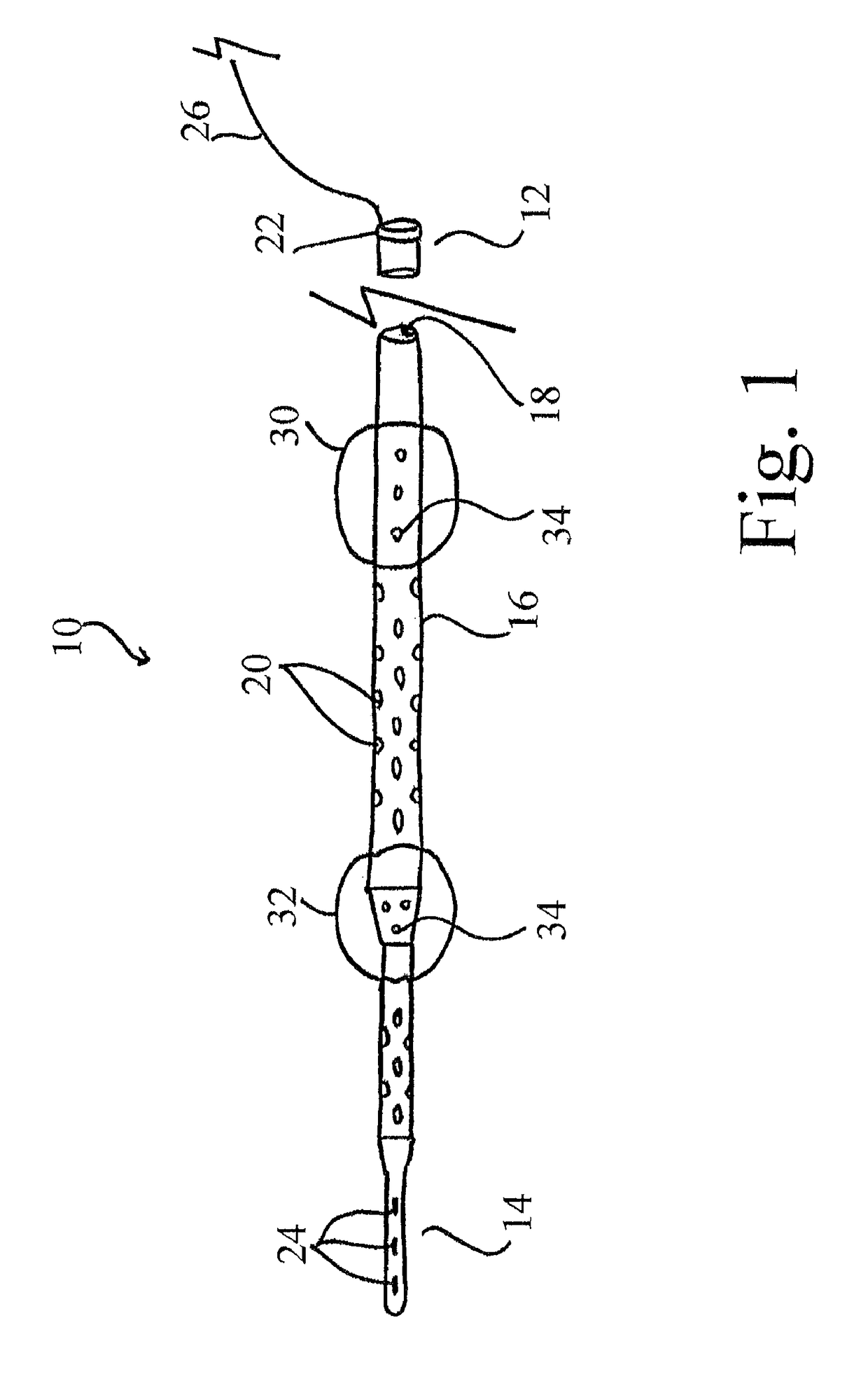
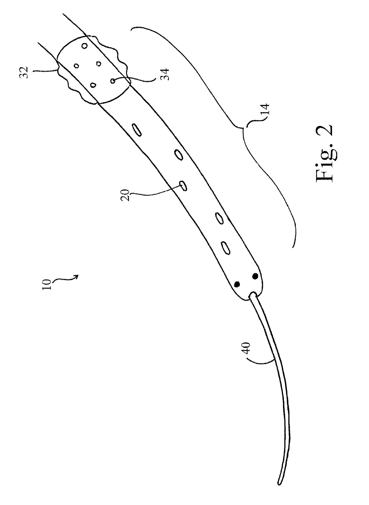
[0027]Methods for delivering a retroperfusion therapy to an ischemic area of a brain are also provided herein. In at least one embodiment, such a method comprises the steps of: identifying the location of a penumbral region within a brain; re-routing arterial blood flow from an artery into the proximal end of a first catheter for receiving arterial blood flow, the first catheter comprising a proximal end for receiving the arterial blood flow, a distal end for allowing the arterial blood flow to flow therethrough and an interior extending between the proximal end and the distal end; inserting a first guidewire into a vein and advancing the guidewire through the vein into the penumbral region of the brain; advancing a second catheter over the first guidewire, through the vein and into the penumbral region of the brain, the second catheter comprising an open proximal end, a distal end, an interior extending between the open proximal end and the distal end, and a plurality of orifices disposed thereon, each of the orifices in fluid communication with the interior of the second catheter; coupling the proximal end of the second catheter with a flow unit, the flow unit comprising an elongated body having an open proximal end configured to couple with the distal end of the first catheter, an open distal end configured to couple with the open proximal end of the second catheter, an interior extending between the open proximal end and the open distal end and configured to allow arterial blood to flow therethrough, and a chamber coupled with the elongated body and configured to regulate the flow rate and pressure of the arterial blood flow flowing through the interior of the flow unit; coupling the distal end of the first catheter with the proximal end of the flow unit such that the interior of the first catheter and the interior of the flow unit are in fluid communication; supplying the penumbral region of the brain with arterial blood flow by allowing the arterial blood to flow in a pulsatile fashion through the first catheter, into and through the interior of the flow unit, into and through the second catheter, and into the vein at the location within the penumbral region; and regulating the pressure and flow rate of the arterial blood flowing through the interior of the elongated body of the flow unit through operation of the chamber.
[0030]The second catheter of the method may further comprise at least one expandable balloon, each of the at least one expandable balloons coupled with the first catheter, having an interior in fluid communication with the interior of the second catheter through one or more pores and adapted to move between an expanded configuration and a deflated configuration. In this at least one embodiment, wherein when the at least one balloon of the second catheter is in the expanded configuration, the at least one balloon of the second catheter occludes the vein and prevents antegrade flow of the arterial blood therethrough. Additionally, at least one embodiment of the method described herein further comprises the step of moving the at least one balloon of the second catheter from the deflated configuration to the expanded configuration in accordance with the pulsatile flow of the arterial blood through the interior of the second catheter.
[0031]In certain embodiments, the step of regulating the pressure and flow rate of the arterial blood flowing through the interior of the elongated body of the flow unit through operation of the chamber is automatically initiated by the remote device when the gathered data falls outside of the one or more programmed parameters. Further, the interior of the elongated body of the flow unit may comprise a diameter and the chamber of the flow unit surrounding at least a portion of the elongated body of the flow unit may comprises an interior defining a volume, and may be adapted to expand when the volume is increased and deflate when the volume is decreased; and the step of regulating the pressure and flow rate of the arterial blood flowing through the interior of the elongated body of the flow unit through operation of the chamber further may comprise adjusting the volume of the interior of the chamber such that the chamber compresses a section of the interior of the elongated body associated with the portion surrounded by the chamber thereby reducing the diameter of the interior of the elongated body.
[0034]In those embodiments of the system further comprising the sheath, the method may further comprise the step of sliding the sheath over the second catheter such that one or more of the plurality of orifices are blocked and arterial blood flow is prevented from flowing through the blocked orifice(s).

Problems solved by technology

As such, stroke survivors as a group have an increased risk of experiencing an additional stroke(s) and, unsurprisingly, have increased mortality and morbidity rates.
Accordingly, the cost of this illness to society in both health care and lost productivity is enormous, and the extended complications associated with surviving even one stroke event adversely influences both quality of life, and the morbidity and mortality of the individual stroke survivor.
In the core zone, which is an area of severe ischemia (blood flow reduced to below 15-20 ml / 100 g / minute), the loss of an adequate supply of oxygen and glucose results in the rapid depletion of energy stores resulting in death of the brain tissue.
As neurons die within a few minutes of oxygen deprivation, neuronal death begins to occur in areas of no blood flow within minutes of stroke onset, thus leaving the tissue of the core ischemic zone unable to function.
However, if reperfusion is not established relatively quickly following the acute attack, over time irretrievable infarction will progressively replace the cells in the penumbral region.
Despite advances in the understanding of stroke pathogenesis, until recently, no specific therapeutic procedures have been available for improving outcomes in acute stroke patients.
However, due to recent therapeutic developments, the morbidity and mortality of acute stroke patients has seen an overall decline.
There is currently little understanding of how to use prophylactic therapies in patients suffering from an acute ischemic stroke.
For example, the rigid time window where the penumbral region remains viable greatly limits the availability of thrombolytic treatment in the majority of cases.
Further, for more than two (2) decades, neurologists have sought a drug that protects ischemic brain tissue from cell death with little success; the list of pharmaceuticals tested in Phase II and Phase III trials is extensive, yet none have proved effective in humans.
Other neuroprotective agents such as radical scavengers, calcium antagonists, sodium or potassium channel blockers, cell membrane stabilizers, anti-inflammatory agents, anti-adhesion molecules, and glycine-, AMPA- and serotonin-receptor antagonists have proven to significantly reduce the infarct volume in animal models, yet also were found ineffective in clinical trials.
One reason such pharmaceutical and / or thrombolytic therapies have been found ineffective in humans is that it is unlikely that the drugs, especially neuroprotective agents, can reach high enough pharmacological levels in the penumbral region to prevent the progression of tissue damage therein prior to the onset of cellular death.
Recent clinical reports suggest that circulation management using RCP in combination with hypothermic circulatory arrest has even decreased the overall rate of stroke and operative mortality associated with aortic arch operations.
Although RCP has been very successful for patients undergoing circulatory arrest in surgery, a bridge reperfusion therapy used in conjunction with thrombolytics and / or other pharmaceuticals for stroke patients does not currently exist.

Method used


Image

  • Systems and methods for selective auto-retroperfusion along with regional mild hypothermia
  • Systems and methods for selective auto-retroperfusion along with regional mild hypothermia
  • Systems and methods for selective auto-retroperfusion along with regional mild hypothermia

Examples


Embodiment Construction

[0057]Reference will now be made to the embodiments illustrated in the drawings and specific language will be used to describe the same. It will nevertheless be understood that no limitation of scope is intended by the description of these embodiments.

[0058]The devices, systems and methods described herein provide for a bridge therapy that is capable of supplying a patient's own oxygenated arterial blood to the compromised penumbral region of the brain via cerebral pulsatile venous retroperfusion. In this manner, the devices, systems and methods described herein facilitate the provision of oxygen-rich blood to the penumbra and thereby extend the window during which the penumbral cells remain viable. Extending the window of viability of the penumbra allows for the use of several new therapies for the treatment of stroke including, without limitation, the delivery of neuroprotective agents and thrombolytic drugs to the cerebral venous system as the agents and drugs will be allowed a s...


PUM


Abstract

Systems and methods for selective auto-retroperfusion along with regional mild hypothermia. In at least one embodiment of a system for providing a retroperfusion therapy to a venous vessel of the present disclosure, the system comprises a catheter for controlling blood perfusion pressure, the catheter comprising a body having a proximal open end, a distal end, a lumen extending between the proximal open end and the distal end, and a plurality of orifices disposed thereon, each of the orifices in fluid communication with the lumen, and at least one expandable balloon, each of the at least one expandable balloons coupled with the body, having an interior that is in fluid communication with the lumen, and adapted to move between an expanded configuration and a deflated configuration, and a flow unit for regulating the flow and pressure of a bodily fluid, and a regional hypothermia system operably coupled to the catheter, the regional hypothermia system operable to reduce and / or regulate a temperature of the bodily fluid flowing therethrough.

Description

PRIORITY[0001]The present application (a) is related to, and claims the priority benefit of, U.S. Provisional Patent Application Ser. No. 61 / 682,351, filed Aug. 13, 2012, and (b) is related to, claims the priority benefit of, and is a continuation-in-part application of, U.S. patent application Ser. No. 13 / 705,101, filed Dec. 4, 2012, which is related to, claims the priority benefit of, and is a continuation application of, U.S. application Ser. No. 12 / 715,100, filed Mar. 1, 2010 and issued as U.S. Pat. No. 8,322,347 on Dec. 4, 2012, which is related to, claims the priority benefit of, and is a continuation application of, U.S. patent application Ser. No. 12 / 715,046, filed Mar. 1, 2010 and issued as U.S. Pat. No. 8,241,248 on Aug. 14, 2012, which is related to, and claims the priority benefit of, U.S. Provisional Patent Application No. 61 / 156,458, filed on Feb. 27, 2009. The contents of each of these applications are hereby incorporated by reference in their entirety into this discl...

Claims


Application Information

Patent Timeline
Patent Type & Authority Patents(United States)
IPC IPC(8): A61M29/00A61B17/12A61M31/00A61F7/12A61B5/00A61B5/0215A61B5/026A61M1/36A61M5/172A61M25/00A61B5/145A61M25/10A61M25/06
CPCA61F7/123A61B5/026A61B5/02152A61B5/02158A61B5/6853A61B17/1204A61B17/12136A61M1/3613A61M1/3621A61M5/172A61B5/145A61M25/007A61M25/1011A61M2025/0002A61M2025/0681A61M2025/1081A61M2205/3368A61M2205/36A61M2210/0693
Inventor KASSAB, GHASSAN S.NAVIA, SR., JOSE A.
Owner CVDEVICES
Learn More