Heterogeneous composite bodies with isolated cermet regions formed by high temperature, rapid consolidation

a composite body and high temperature technology, applied in the direction of shaft and bearing, rotary bearing, metal-working apparatus, etc., can solve the problems of inability to meet the requirements of cemented tungsten carbide, catastrophic failure, and inconsistent manufacturing quality of silicon nitride components, so as to improve toughness and impact resistance of the heterogeneous body, increase the spacing, and quickly abrade away

Active Publication Date: 2018-04-17
POWDERMET
View PDF18 Cites 172 Cited by
  • Summary
  • Abstract
  • Description
  • Claims
  • Application Information

AI Technical Summary

Benefits of technology

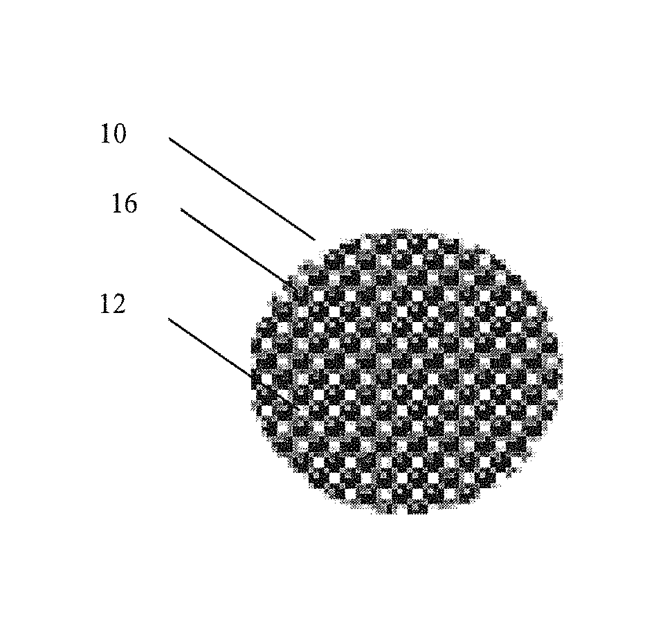
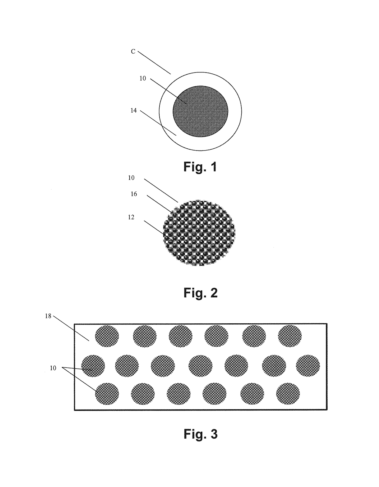
[0016]Generally, the ductile metal matrix precursor is substantially uniform in composition and the deposit thickness of the metal on the ceramic rich cermet region of the ceramic-metallic composites is maintained at desired thickness so that the desired uniformity of ceramic rich cermet region spacing, size, integrity, orientation and composition in the heterogeneous body is obtained; however, this is not required. The coating thickness of the metal coating on the ceramic-metallic composites generally controls, to a significant degree, the spacing between the ceramic rich cermet regions. Increasing the thickness of the metal coating generally increases the amount of spacing between the ceramic rich cermet regions in the finished heterogeneous body.
[0017]As formed, a layer of approximately lenticular ceramic rich cermet regions is typically embedded slightly below the surface of a layer of the matrix phase. In use, the matrix phase layer over the ceramic rich cermet regions is usually quickly abraded away, thus exposing the top surfaces of the ceramic rich cermet regions. The thusly exposed obverse faces of the tiled ceramic rich cermet regions present a hard wear resistant surface that generally covers substantially all of the heterogeneous body, and appears in plain view to be substantially continuous. The reverse faces of the ceramic rich cermet regions are generally firmly bonded over the entire width of the ceramic rich cermet regions to the heterogeneous body. The isolated ceramic rich cermet regions are thus firmly bonded over a wide area by the matrix phase to the heterogeneous body. The toughness and impact resistance of the heterogeneous body are improved by the matrix phase, which in cross-section is generally substantially continuous.
[0018]The heterogeneous nature of the heterogeneous body provides substantial advantages. The heterogeneous body according to the present invention can be used to provide a tool with hardness and wear resistance characteristics that would require a much higher ceramic content if the body were not homogeneous. At the same time, the heterogeneous body provides a tool with strength, toughness, and impact resistance characteristics that are much higher than would be possible with a homogeneous body that exhibits the same hardness and wear resistance.
[0019]The body of material is generally formed as an individual component and is typically formed in a cylindrical shape, but can be formed as a more complex shape or near-net shape. The ductile metal matrix enables easy machining of the component to desired dimensions and tolerances. Furthermore, the small size of the cermet particles allows for the material to be machined to a smooth finish. This makes the invention ideal in low-friction applications, particularly rolling and sliding contact bodies in bearings.

Problems solved by technology

Significant investigation has been conducted on silicon nitride bearing components; however, manufacturing quality of silicon nitride components is inconsistent as components tend to fail randomly and catastrophically as a result of internal defects.
Although the fracture toughness of cemented tungsten carbide has been somewhat improved over the years, it is still a limiting factor in demanding industrial applications where cemented tungsten carbide inserts often exhibit gross brittle fracture that leads to catastrophic failure.
Applications of cemented tungsten carbide are limited to this envelope.
Additionally, traditional tungsten carbide lacks in its ability to acquire a smooth surface finish as a result of large particle size within a tungsten carbide compact.

Method used


Image

  • Heterogeneous composite bodies with isolated cermet regions formed by high temperature, rapid consolidation
  • Heterogeneous composite bodies with isolated cermet regions formed by high temperature, rapid consolidation
  • Heterogeneous composite bodies with isolated cermet regions formed by high temperature, rapid consolidation

Examples


example 1

[0041]A ceramic-metallic composite was produced with a composition of about 45-50 wt % TiN, about 40-45 wt % Co—Mo—Cr, and about 10 weight percent niobium binder. The ceramic-metallic composite was consolidated using spark plasma sintering above about 1000° C. The consolidated material exhibited a hardness of 1278 HV(300) and coefficients of friction of less than about 0.10 in diesel fuel, and about 0.40 in dry contact with steel. No material wear was observed after friction testing with pin on disk tribometer.

example 2

[0042]The material formed in Example 1 was machined using electrical discharge machining into an about 2 in. wide, ¼ in. thick flat thrust bearing with an internal diameter of about 1 in.

example 3

[0043]The material formed in Example 1 was precision-machined using electrical discharge machining into about a 1 in. tall hollow cylinder with about ⅛ in. wall thickness. This cylindrical piece was interference fitted into a steel bushing to form a cermet lined bushing.


PUM

PropertyMeasurementUnit
widthaaaaaaaaaa
grain sizeaaaaaaaaaa
volume percentaaaaaaaaaa

Abstract

A heterogeneous composite consisting of near-nano ceramic clusters dispersed within a ductile matrix. The composite is formed through the high temperature compaction of a starting powder consisting of a core of ceramic nanoparticles held together with metallic binder. This core is clad with a ductile metal such that when the final powder is consolidated, the ductile metal forms a tough, near-zero contiguity matrix. The material is consolidated using any means that will maintain its heterogeneous structure.

Description

[0001]The present invention claim priority on U.S. Provisional Patent Application Ser. No. 61 / 994,483 filed May 16, 2014, which is incorporated herein by reference.[0002]This invention was made with U.S. government support under Contract No. N68335-14-C-0051 awarded by U.S. Navy. The U.S. government has certain rights in the invention.FIELD OF THE INVENTION[0003]The invention relates in general to heterogeneous composites comprised of non-angular approximately spherical-, lenticular-, oval-, or elliptical-shaped ceramic rich ceramic-metallic (“cermet”) regions bonded in a ductile matrix. More particularly, the invention relates to heterogeneous composites having a bi-modal microstructure comprised of a ductile metal matrix and a plurality of generally oval- or spherical-shaped ceramic rich cermet regions embedded in the ductile metal matrix. The ceramic rich cermet regions are configured in a generally tiled, but substantially separated, relationship so as to present a tightly bonde...

Claims


Application Information

Patent Timeline
Patent Type & Authority Patents(United States)
IPC IPC(8): B22F3/20C22C32/00F16C33/00B23H5/12B22F3/24C04B35/58C04B35/56B23P13/02B23H7/00B23H1/08B23H5/04B22F1/02B22F3/105B22F3/14B22F3/15B22F3/17B22F3/18C22C29/00F16C17/00F16C19/00F16C33/04B22F1/17
CPCB23H5/12B22F3/105B22F3/14B22F3/15B22F3/17B22F3/18B22F3/20B22F3/24B23H1/08B23H5/04B23H7/00B23P13/02C04B35/5626C04B35/58014C22C29/00C22C32/00F16C33/00B22F1/025F16C2206/80F16C17/00F16C19/00F16C33/043B22F1/17C22C29/005C22C29/065C22C29/08C22C29/14
Inventor GROGAN, MARKDOUD, BRIANSHERMAN, ANDREW
Owner POWDERMET
Why Eureka
Try Eureka