
Apparatus and method for operating internal combustion engines from variable mixtures of gaseous fuels

Inactive Publication Date: 2011-11-01
RGT UNIV OF CALIFORNIA
View PDF11 Cites 3 Cited by
  • Summary
  • Abstract
  • Description
  • Claims
  • Application Information

AI Technical Summary

Benefits of technology

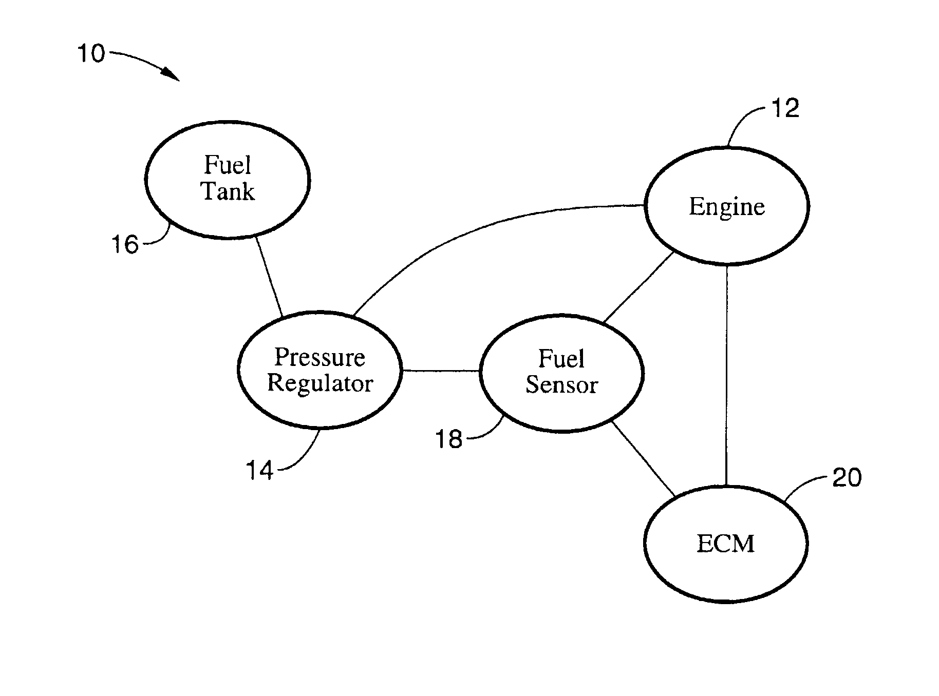
[0027]The ECM therefore meters an appropriate volume of gaseous fuel into each cylinder in response to the composition of the available gaseous fuel, along with traditional fuel metering determinants such as throttle setting, RPM, temperature, and the like. Incorporating gaseous fuel composition sensing and the ability to adjust fuel metering and other optional combustion parameters in response to fuel composition results in a VGF engine according to the present invention which is capable of being efficiently operated from a source of gaseous fuel which contains any proportion of natural gas and hydrogen.
[0028]An object of the invention is to expedite the transition from the use of fossil fuels to a renewable hydrogen energy source by providing an engine capable of operating on any mixture of either fuel source.

Problems solved by technology

The adoption of electrical vehicles, however, has proceeded slowly and a number of electric vehicle manufacturers have discontinued sales.
Despite the enormous expenditures to develop electric vehicles and recharging equipment, the fundamental shortcomings of the technology and infrastructure have never been overcome.
It should be appreciated that, although electrical energy may be readily converted to mechanical energy without generating high emission levels, electrical energy storage within batteries has many inherent drawbacks, including the time required to recharge a battery, the cost of batteries, and the weight per unit of energy stored within a battery.
However, the drawbacks associated with emissions and other environmental concerns, as well as the non-renewable nature of these fossil fuels, remain.
A number of disadvantages exist, however, with regard to the adoption of on-board reforming for the purposes of facilitating the introduction of vehicles which operate from hydrogen fuel cells.
The adoption of hydrogen as an energy source has been a slow process, perhaps due in part to the inherent difficulty of changing an existing infrastructure to accommodate the use of hydrogen.
The present infrastructure is lacking in both vehicles and fueling facilities that are capable of using, or distributing, hydrogen.
Changing the present infrastructure to provide hydrogen distribution while synchronously developing and deploying hydrogen-fueled vehicles is a formidable challenge.
One key difference between these fuels, however, is the energy density contained per cubic foot.
Consequently, the adoption of hydrogen gas as a “replacement” for natural gas would not solve the inherent infrastructure problems associated with the introduction of a new incompatible fuel source, and the conversion of vehicles to hydrogen could only be expected after an adequate hydrogen fuel distribution network had been established.
First, although the hydrogen combustion process involves burning increased volumes of gaseous fuel, the resulting emissions contain lower levels of air pollutants and carbon dioxide than a comparable engine generating a give horsepower when operating from a natural gas fuel source.
Second, hydrogen is a renewable fuel source that may be generated from a number of low-cost processes, whereas natural gas is a limited fossil fuel resource.
It will be appreciated that convenient operation of a hydrogen vehicle over distances requiring refueling has not been possible thus far due to a lack of hydrogen fuel distribution facilities.
Experimental hydrogen vehicles are therefore only capable of operating within a limited commute radius about a facility-based refueling station.
Efficiency is extremely important for hydrogen fueled vehicles, as the available fuel storage volume limits vehicle range.
This imposes significant limits on the fuel mixtures that can be employed.

Method used


Image

  • Apparatus and method for operating internal combustion engines from variable mixtures of gaseous fuels
  • Apparatus and method for operating internal combustion engines from variable mixtures of gaseous fuels
  • Apparatus and method for operating internal combustion engines from variable mixtures of gaseous fuels

Examples


example 1

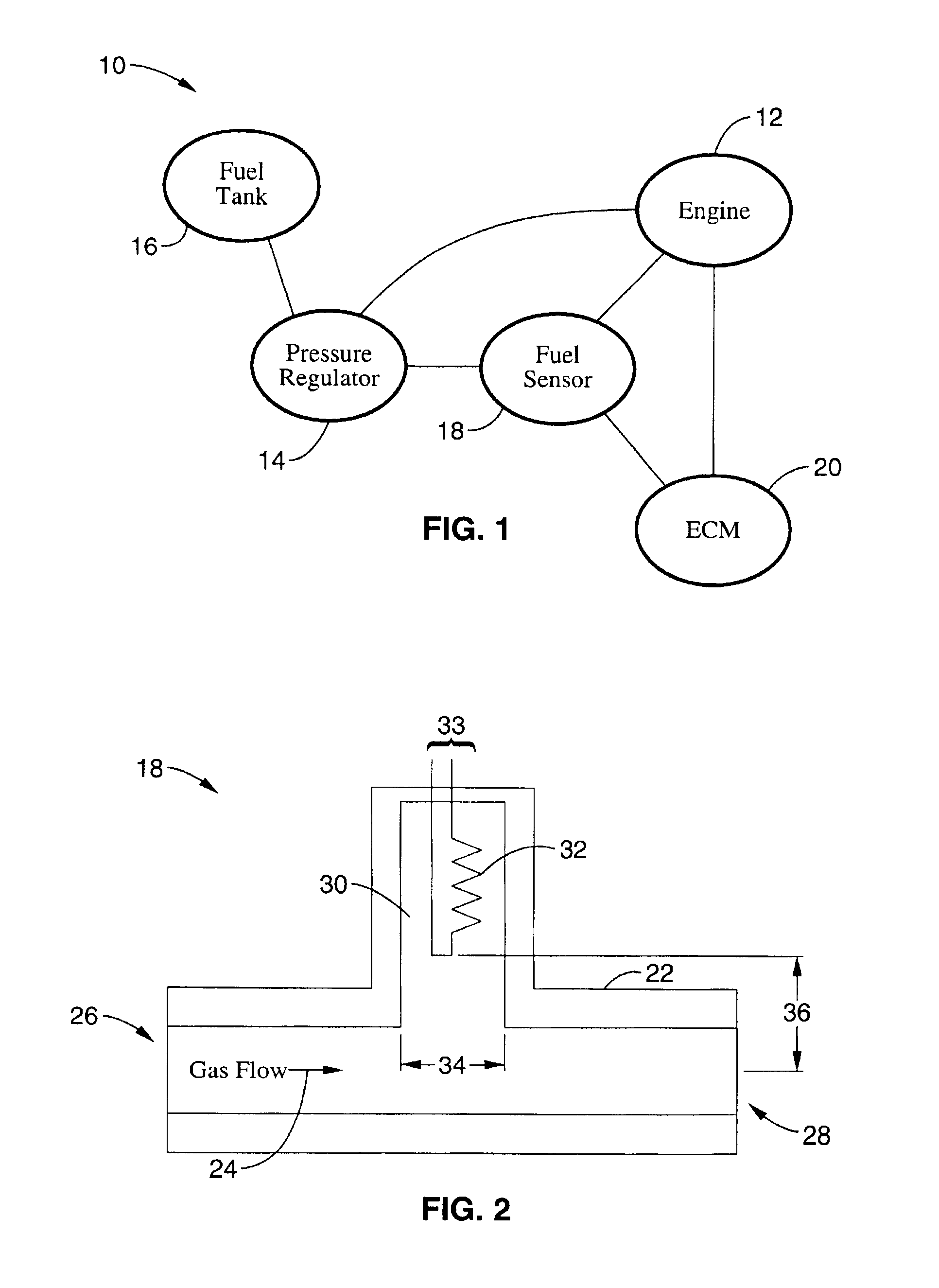
[0059]Care should be taken in designing the structure of the fuel sensor as the internal diameter 34 of the branched line for the sensing element and the distance between sensor element and fuel flow line 36 have been found to be important considerations in providing an adequate sensor signal level with a sufficiently rapid response time. By way of example, a suitable fuel sensor structure was fabricated with a chamber having a diameter 34 of about one-half centimeter (0.53 cm actual diameter used in testing) whereas filament 30 was offset 36 from the center of the gas flow passageway by a distance of about two centimeters (2.3 cm actual offset utilized in testing). It will be appreciated therefore that high signal levels and low susceptibility to gaseous flow rate were obtained with the offset distance being approximately four times (4×) that of the chamber diameter. It should also be appreciated, however, that the filament may be isolated from the convective flow using alternative...

example 2

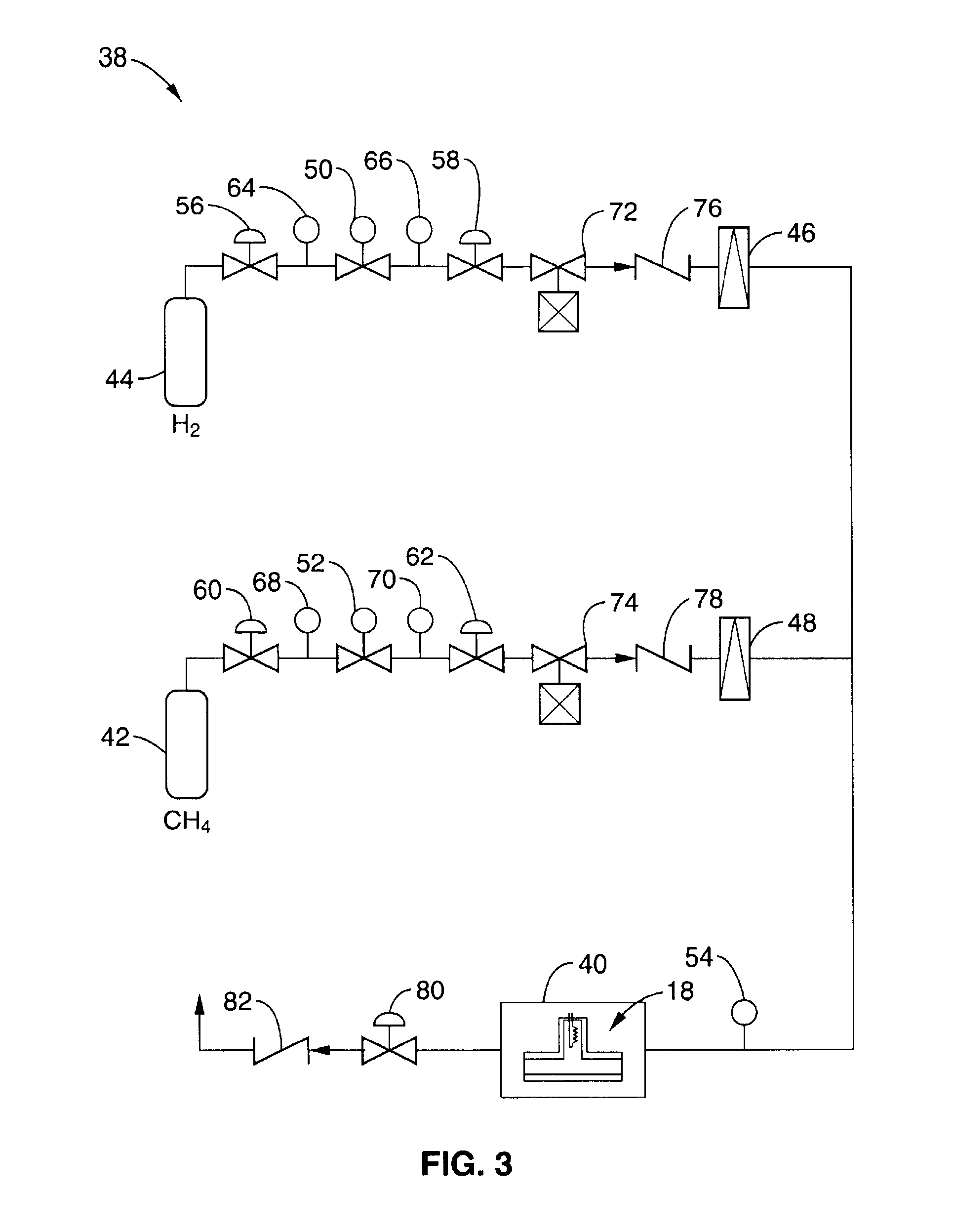
[0061]FIG. 3 illustrates a sensor test bench that was utilized for testing gaseous fuel composition sensor 18 as shown in FIG. 2. Test measurements were taken with fuel composition sensor 18 positioned within a temperature controlled oven 40. Oven temperature was measured utilizing an integrated circuit temperature sensor, specifically a model LM35 from National Semiconductor Incorporated®. The temperature sensor was utilized to control the temperature in conjunction with a personal computer to provide feedback for any desired value from ambient temperature to about 350 degrees Kelvin. Two kinds of calibration were performed with sources of pure methane 42 or pure hydrogen 44 that could be fed into fuel composition sensor 18 simultaneously, or sequentially, with the operation of a solenoid valve. The desired gas flow rate was adjusted by a needle valve and a ball flow meter 46, 48 for a range of flow situations from a static, no flow condition, to about two liters per minute. A cali...


PUM


Abstract

An apparatus and method for utilizing any arbitrary mixture ratio of multiple fuel gases having differing combustion characteristics, such as natural gas and hydrogen gas, within an internal combustion engine. The gaseous fuel composition ratio is first sensed, such as by thermal conductivity, infrared signature, sound propagation speed, or equivalent mixture differentiation mechanisms and combinations thereof which are utilized as input(s) to a “multiple map” engine control module which modulates selected operating parameters of the engine, such as fuel injection and ignition timing, in response to the proportions of fuel gases available so that the engine operates correctly and at high efficiency irrespective of the gas mixture ratio being utilized. As a result, an engine configured according to the teachings of the present invention may be fueled from at least two different fuel sources without admixing constraints.

Description

CROSS-REFERENCE TO RELATED APPLICATIONS[0001]This application claims priority from U.S. provisional application serial No. 60 / 225,017 filed on Aug. 11, 2000, incorporated herein by reference.STATEMENT REGARDING FEDERALLY SPONSORED RESEARCH OR DEVELOPMENT[0002]This invention was made with Government support under Contract No. DE-FC36-94G010039 awarded by the U.S. Department of Energy. The Government has certain rights in this invention.REFERENCE TO A COMPUTER PROGRAM APPENDIX[0003]Not ApplicableBACKGROUND OF THE INVENTION[0004]1. Field of the Invention[0005]The invention pertains generally to internal combustion engines utilizing gaseous fuels, and more particularly to a method and apparatus for operating an internal combustion engine at high efficiency from an arbitrary mixture of multiple gaseous fuels such as hydrogen and natural gas.[0006]2. Description of the Background Art[0007]The current use of fossil fuels, such as gasoline, diesel fuel, and natural gas, to power various for...

Claims


Application Information

Patent Timeline
IPC IPC(8): F02B43/00F02B43/10F02B51/00F02D19/08F02G1/043G01N25/18
CPCF02B43/00F02B43/10F02B51/00F02G1/043F02M21/0215F02D19/0644F02D19/087F02D19/024F02D19/029F02G2254/11Y02T10/36Y02T10/32G01N25/18Y02T10/30
Inventor HEFFEL, JAMES W.SCOTT, PAUL B.PARK, CHAN SEUNG
Owner RGT UNIV OF CALIFORNIA
Learn More