

Simultaneously desulfurization and denitration wet ammonia flue gas cleaning technology and system thereof
A desulfurization and denitrification, flue gas technology, applied in separation methods, chemical instruments and methods, dispersed particle separation and other directions, can solve the problems of increased resistance of desulfurization and denitrification equipment, bulky desulfurization and denitrification equipment, and high construction and operating costs, and achieves the realization of Harmless and resource utilization, overcoming the effects of low denitrification efficiency and high absorbent utilization rate
- Summary
- Abstract
- Description
- Claims
- Application Information
AI Technical Summary
Problems solved by technology
Method used
Image

Examples
Embodiment Construction
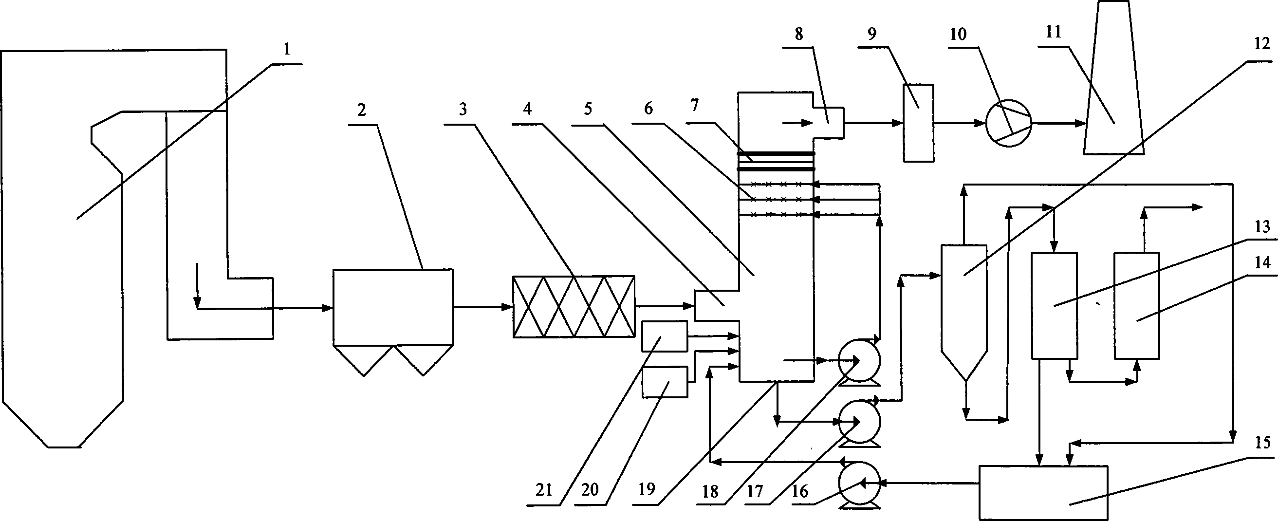
[0030] Below for a coal-fired power station boiler unit, the present invention will be further described in detail in conjunction with the accompanying drawings:
[0031] The wet ammonia flue gas cleaning system with simultaneous desulfurization and denitrification shown in the figure includes a pre-dust removal device 2 arranged on the outlet flue of the coal-fired boiler unit 1 and a desulfurization and denitrification tower 5 for the flue gas reaction main device. The pre-dust removal device 2 adopts an electrostatic precipitator with a wire-plate four-stage electric field structure, which can collect more than 99.5% of dust particles in the flue gas. A hydrogen peroxide or ozone injection device 3 is arranged on the flue between the pre-dust removal device 2 and the desulfurization and denitrification tower 5. This device can be an atomizing injector with a grid structure. This atomizing injector generally includes 1 to 5 One main pipe, 4 to 10 branch pipes are arranged at...
PUM
 Abstract
Description
Claims
Application Information