Nanosized carbon material-activated carbon composite
A carbon composite material, activated carbon technology, applied in nanotechnology, carbon compounds, nanotechnology and other directions, can solve problems such as difficult to formulate polymers
- Summary
- Abstract
- Description
- Claims
- Application Information
AI Technical Summary
Problems solved by technology
Method used
Image
Examples
Embodiment 1
[0282] Activated carbon used as support was obtained from VERSATEC SDN (Malaysia). It is produced from palm kernel husks as a waste product in palm production. After activation, it contained, in addition to carbon, a considerable amount (about 6 wt%) of silicate and a trace amount of iron as iron silicate. Activation is carried out in dedicated steps by methods including partial oxidation and steam treatment.
[0283] The activated carbon was pulverized and screened to obtain a uniform particle size distribution with an average particle size of about 0.5 mm. Carbonized precursors typically obtained from palm kernel shells have about 1081 m 2 / g of BET surface area, and 0.365cm 3 / g of pore volume.
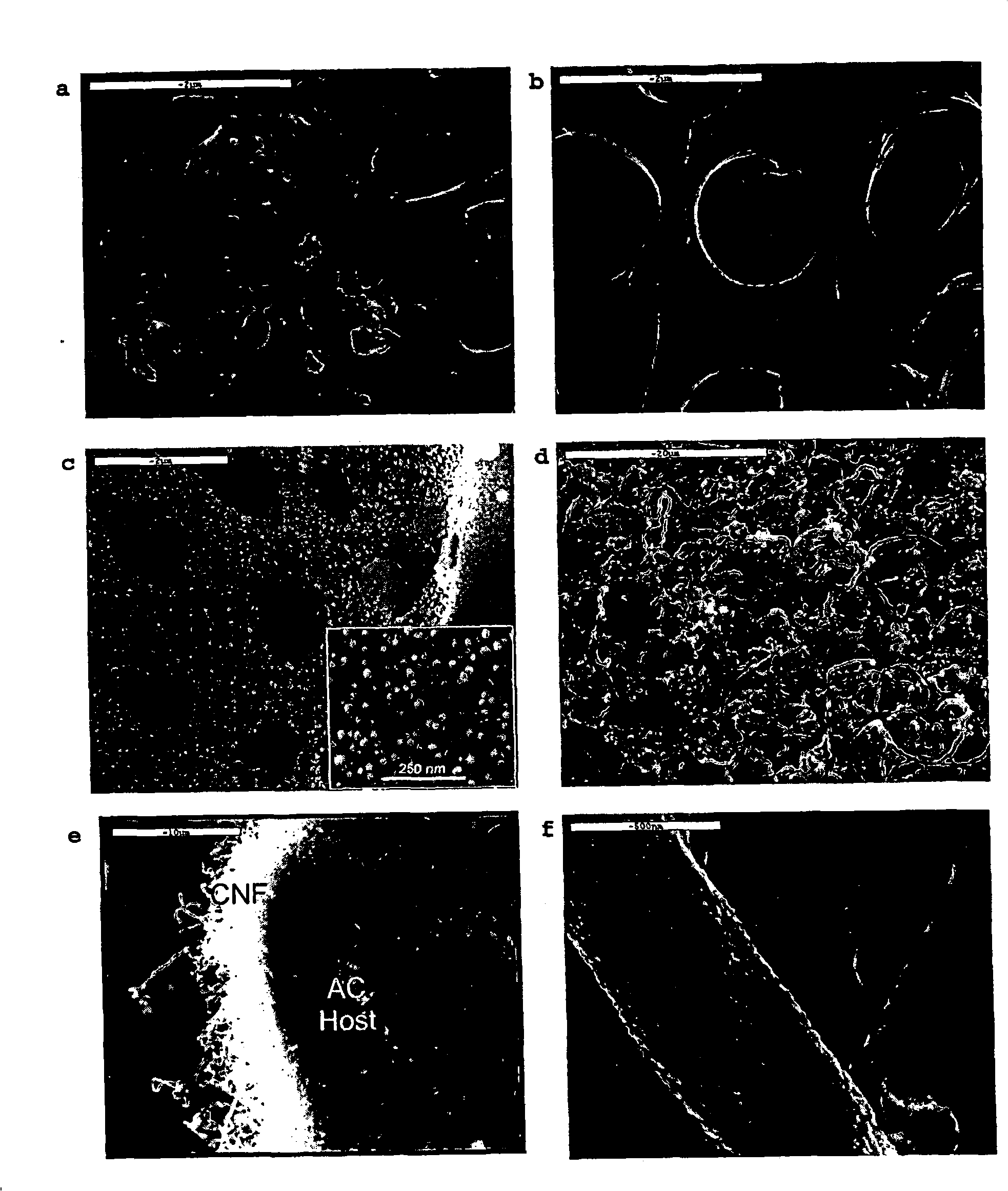
[0284] exist figure 1 A scanning electron microscope image (SEM) of the activated carbon thus obtained is given in a.
[0285] To prepare a host for a given hierarchical structure, the resulting AC was mildly oxidized in air at 400 °C for 4 h. The mild oxidation is believed ...
Embodiment 2
[0300] In this example, as described in Example 1, untreated AC, AC mildly oxidized at 400°C (referred to as "AC-400"), and CNF / AC composite (referred to as "NAC") were compared ) for HPA (heteropolymolybdic acid) [PMo 12 O 40 ] 3- and dichromate [Cr 2 O 7 ]2- adsorption capacity. 10 mg of each adsorbent material was suspended in 1.5 ml of HPA or dichromate solution. The starting concentration was 1 mM. The suspension was stirred at room temperature for 1 hour. The concentration of [PMo] was determined photometrically at a selected wavelength of 325 nm. Adsorption tests were performed in Eppendorf-Caps (volume 2.0 ml polyethylene material). No pH adjustment was made since the pH itself had produced dissolved HPA or chromate, respectively (about 3.0 for HPA solution and about 8.5 for chromate).
[0301] The results are given in Table 4 below.
[0302] Table 4
[0303] Adsorption of dichromate or molybdate species in aqueous solution
[0304]
BET
...
Embodiment 3
[0312] Example 3: Synthesis of CNTs on Carbon Black (Nanoscale Support)
[0313] 10.0 g of commercial carbon black (DEGUSSA PRINTEX 40) was suspended in 200 ml of concentrated ammonium hydroxide solution and stirred in an ultrasonic bath (600 W, water as transfer agent) at 300 K (27 °C) for 30 min. The resulting colloidal suspension was separated from the liquid phase by centrifugation and the wet solids were placed in a vertical 25 mm (internal diameter) tubular quartz reactor fixed in a 100 cm long tube furnace. Under the carbon black filler, 0.2 g of Ni-formate filler diluted in 1 g of boron nitride was placed.
[0314] The reactor was flushed with nitrogen and then fed a reactive gas atmosphere of 5% CO in nitrogen at a flow rate of 100 ml / min. The reactor was heated to 573K (300°C) at 5K / min and held at this temperature for 3 hours, then heated to 823K (550°C) at 5K / min and held at this temperature for 3 hours. The gas was replaced with pure nitrogen and cooled under ni...
PUM
| Property | Measurement | Unit |
|---|---|---|
| diameter | aaaaa | aaaaa |
| diameter | aaaaa | aaaaa |
| size | aaaaa | aaaaa |
Abstract
Description
Claims
Application Information
 - R&D
- Intellectual Property
- Life Sciences
- Materials
- Tech Scout
- Unparalleled Data Quality
- Higher Quality Content
- 60% Fewer Hallucinations
Browse by: Latest US Patents, China's latest patents, Technical Efficacy Thesaurus, Application Domain, Technology Topic, Popular Technical Reports.
© 2025 PatSnap. All rights reserved.Legal|Privacy policy|Modern Slavery Act Transparency Statement|Sitemap|About US| Contact US: help@patsnap.com


