Gas desulfurization and denitration method
A gas and denitrification technology, applied in chemical instruments and methods, separation methods, air quality improvement and other directions, can solve the problems of difficult catalyst regeneration, poor adsorption capacity, and difficulty in applying smoke-containing systems, etc., to improve the utilization rate of ultraviolet light and photocatalysis. Efficiency, low resistance channel, effect of enhancing photocatalytic effect
- Summary
- Abstract
- Description
- Claims
- Application Information
AI Technical Summary
Problems solved by technology
Method used
Image
Examples
Embodiment 1
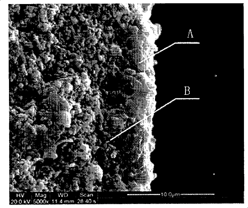
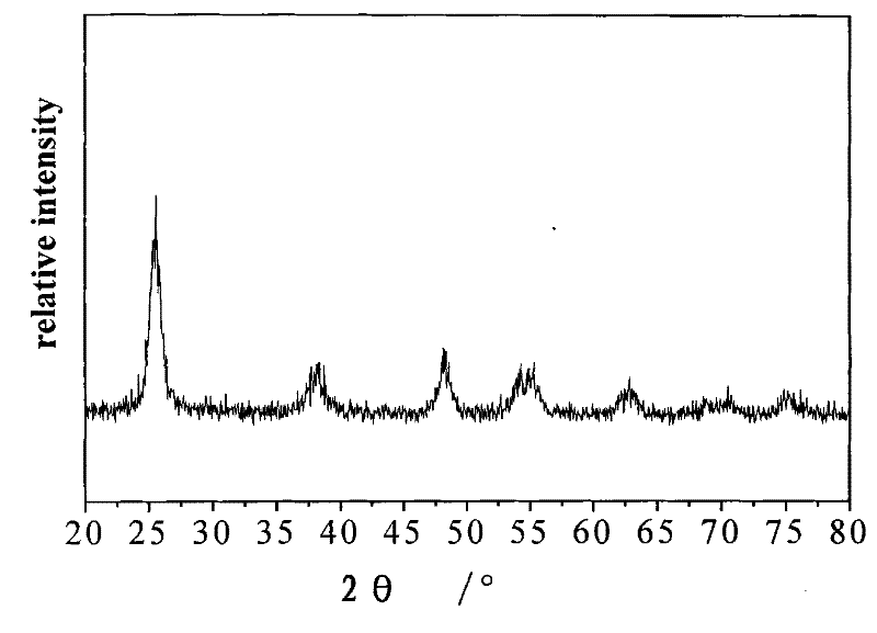
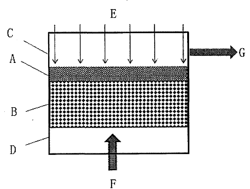
[0028] The photocatalytic film is prepared according to the method reported in the patent 200810023906.X, and the particle size of the sol is 5nm, 1.0mol L -1 Add triblock copolymer templating agent (EO) to titanium sol 20 (PO) 70 (EO) 20 (Molecular weight is 5800g·mol -1 ) to obtain a stable coating solution. Then use the dip coating technology to coat the film, dry the wet film in the air, dry it, and calcinate it at 400°C to obtain a titanium dioxide ceramic ultrafiltration membrane with a pore size of 5nm. Its microstructure is composed of porous active layers with different functions, A is the photocatalytic active layer, and B is the separation active layer. like figure 1 As shown, the material of the photocatalytic active layer is anatase TiO 2 ,like figure 2 shown. Its thickness is 3μm, the pore diameter is 5nm, the porosity is 60%, and the specific surface area is 150m 2 .g -1 ; The separation layer is Al with a pore size of 200nm 2 o 3 Ceramic membrane w...
Embodiment 2
[0030] The photocatalytic active layer is made of anatase TiO 2 , with a thickness of 100nm, a pore diameter of 2nm, a porosity of 60%, and a specific surface area of 210m 2 .g -1 ; The separation layer is a stainless steel sintered body (35% porosity) with a pore diameter of 100 nm. The gas to be treated contains SO 2 (concentration of 2ppm) and dust gas mixture, the gas mixture is pressurized to 0.8MPa, pressed through the separation active layer to remove dust and other impurities, and reaches the photocatalytic active layer, SO 2 Adsorbed on the photocatalytic active layer, a photocatalytic oxidation reaction occurs under the irradiation of ultraviolet light to generate SO 4 2- , SO 2 The removal rate was 94%, with SO 4 2- Enriched in the catalytic active layer, when the removal rate was reduced to 88%, stop the air intake, and use compressed air (1.8MPa) to purge 3 times from the reverse direction, and then use water vapor to press through the membrane layer from...
Embodiment 3
[0032] The photocatalytic film used is prepared according to the method reported in the patent ZL 200610037611.9. The specific method is to use 1.8 μm isooctane / formamide emulsion as a template, disperse it into titanium sol to form a film-making liquid, and then use dip coating technology Membrane coating: coating the membrane-forming solution on the surface of an alloy membrane (40% porosity) with a pore diameter of 5 μm, and after removing the template at 60° C., calcining at 400° C. to obtain a titanium dioxide ceramic ultrafiltration membrane with a pore diameter of 1.1 μm. The material of the photocatalytic active layer is N-doped anatase TiO 2 ,like Image 6 As shown, its N content is 1%, its thickness is 30 μm, and its porosity is 50%; the gas to be treated is a gas mixture containing NO (concentration is 2ppm) and dust, and the gas is mixed under the pressure of 0.2MPa, after separation activity The layer removes impurities such as dust and reaches the photocatalytic...
PUM
 Abstract
Description
Claims
Application Information
 - R&D
- Intellectual Property
- Life Sciences
- Materials
- Tech Scout
- Unparalleled Data Quality
- Higher Quality Content
- 60% Fewer Hallucinations
Browse by: Latest US Patents, China's latest patents, Technical Efficacy Thesaurus, Application Domain, Technology Topic, Popular Technical Reports.
© 2025 PatSnap. All rights reserved.Legal|Privacy policy|Modern Slavery Act Transparency Statement|Sitemap|About US| Contact US: help@patsnap.com


