Treatment process for garbage leachate

A technology for landfill leachate and a treatment method, which is applied in the field of landfill leachate treatment, can solve the problems of a drop in pH value of an anaerobic system, poor anaerobic reaction effect, large investment and operating costs, etc., so as to promote the hydrolysis and degradation process, avoid the The effect of biodegradable load and low investment and operation cost

Active Publication Date: 2009-05-13
浙江永峰环保科技股份有限公司 +1
View PDF2 Cites 38 Cited by
  • Summary
  • Abstract
  • Description
  • Claims
  • Application Information

AI Technical Summary

Problems solved by technology

[0007] 1. In the prior art, in the step of anaerobic treatment of landfill leachate, an integrated anaerobic reactor, such as a UASB reactor, is mainly used. However, due to unstable biodegradation in this integrated anaerobic reactor load, causing acid-producing bacteria to produce too much VFA (volatile fatty acid), causing the pH value of the anaerobic system to drop, affecting the activity of methanogenic bacteria, thereby affecting the removal efficiency of the entire anaerobic system; in addition, the prior art anaerobic reaction The oxidation-reduction potential (ORP) in the treatment process is relatively high, so the effect of its anaerobic reaction, that is, the effect of hydrolyzing and degrading organic matter in landfill leachate is not ideal, especially when encountering macromolecular organic matter that is difficult to degrade and hydrolyze. The effect of anaerobic reaction will be even worse, so that the subsequent treatment effect cannot be better guaranteed;
[0008] 2. The ammonia nitrogen removal method mentioned in the method whose notification number is CN100398470C is a physical treatment method. After the landfill leachate is alkalized, the nitrogen is partially denitrified through a circulating blow-off pool and a blow-off tower. Although the blow-off method using the blow-off tower has High ammonia nitrogen removal efficiency, but the investment of the ammonia nitrogen stripping tower is very large. During operation, not only a large amount of alkaline agent needs to be added to adjust the pH value of the leachate to 9-11, but also the circulating stripping tower needs more High gas-liquid ratio (generally above 2000:1); in addition, ammonia nitrogen physical stripping requires extremely high water temperature, especially in winter operation, if the circulating water is not heated, its removal efficiency will not be guaranteed. Therefore, the ammonia nitrogen stripping method not only has the disadvantages of high investment and operation cost and complicated control mode, but also because the tail gas containing a large amount of ammonia after deammonization is difficult to treat, it is easy to cause secondary pollution. If the ammonia gas blown out is absorbed and treated , this part of the investment and operating costs are also relatively large; the method for removing ammonia nitrogen proposed by the publication number CN101234836A is a nitrification and denitrification process, which is a biological treatment method. Although this biological treatment method can overcome some defects of the stripping method, its In terms of ammonia nitrogen removal rate and energy consumption, it still has not reached the optimal state
[0009] 3. None of the methods disclosed or authorized above involve the standard treatment of concentrates in membrane separation processes such as NF nanofiltration or RO reverse osmosis, because NF nanofiltration or RO reverse osmosis is a physical separation through a semi-permeable membrane Concentrate the pollutants in the water to one end, and the permeate can be discharged up to the standard, but because the content of organic matter in the influent water is still high, after membrane separation, most of the organic matter and soluble inorganic salts exist in the concentrated liquid, Moreover, this part of organic matter is mainly refractory organic matter such as humic acid. Even if the concentrated solution is returned to the front end of the process system for a series of treatments, it cannot be effectively removed. This part of refractory organic matter and soluble inorganic salts will be in the system. Enrichment affects the operation of the system, causing the effluent to fail to meet the standard, and eventually leads to the collapse of the system

Method used


Image

  • Treatment process for garbage leachate
  • Treatment process for garbage leachate
  • Treatment process for garbage leachate

Examples


Embodiment Construction

[0022] The present invention will be further described below in conjunction with accompanying drawing and specific embodiment:

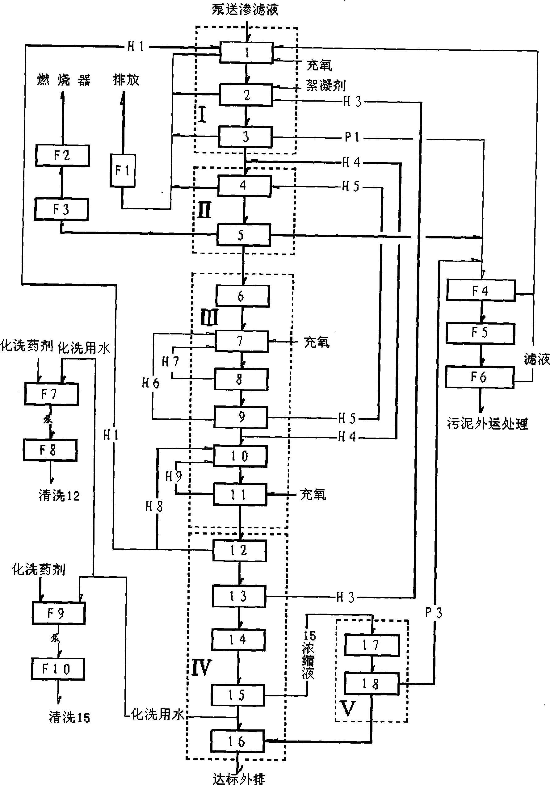
[0023] As shown in the accompanying drawings, the landfill leachate treatment method of the present invention comprises the following steps:

[0024] One. First, the present invention pumps leachate into the micro-aerobic biosorption pool 1 in the micro-aerobic biosorption system 1 through the lifting pump arranged in the garbage storage pit, and the micro-aerobic biosorption pool 1 is mixed with post-process The excess sludge H1 discharged from the MBR membrane separation unit 12 in the first section can absorb organic matter in the water while being slightly aerated and stirred, and the incoming water contains a large amount of easily biochemical substances, and the nitrification sludge is used for denitrification , to remove part of the nitrate nitrogen, the hydraulic retention of the landfill leachate in the microaerobic biosorption tank 1 is 1 t...


PUM


Abstract

The invention discloses a method for treating landfill leachate, which orderly comprises flocculation precipitation pretreatment, hydrolysis pre-acidification treatment, anaerobic treatment, aerobic treatment comprising shortcut nitrification-denitrification and secondary nitrification-denitrification, membrane separation treatment and oxidation flocculation treatment. The method has the advantages of having higher removal rate of ammonia nitrogen and lower energy consumption, realizing the up-to-standard discharge of leachate concentrated solution, ensuring sound operation of the whole system, greatly lowering the oxidation-reduction potential in the anaerobic reaction, and improving the anaerobic treatment effect, thereby making the landfill leachate fully meet the first-level discharge standard of the Integrated Wastewater Discharge Standard.

Description

Technical field: [0001] The invention relates to a method for treating landfill leachate, in particular to a landfill leachate treatment method capable of treating landfill leachate produced in a waste incineration power plant and reaching the first-level discharge standard of the "Comprehensive Sewage Discharge Standard" (GB8978-1996). method. Background technique: [0002] With the rapid development of China's economy and the continuous improvement of people's living standards, the output of urban domestic waste in China is also increasing rapidly. At present, the sanitary landfill method, composting method and waste incineration power generation treatment method of urban waste have become widely used at home and abroad. The garbage disposal method used. Compared with the sanitary landfill and composting methods, the waste incineration power generation treatment method has great advantages in terms of reduction, harmlessness, and resource utilization, especially in areas ...

Claims


Application Information

Patent Timeline
Patent Type & Authority Applications(China)
IPC IPC(8): C02F9/14C02F3/30C02F1/52C02F1/44
Inventor 杨青淼
Owner 浙江永峰环保科技股份有限公司
Why Eureka
Try Eureka