
Biomass gasification apparatus

A technology of biomass and gasification equipment, which is applied in the direction of gasification process, biofuel, educts, etc., can solve the problems of uneven distribution of gasification agent, failure, insufficient synthetic gas, etc., and achieve the goal of increasing the operating temperature range Effect

Active Publication Date: 2009-09-23
NAGASAKI INSTITUTE OF APPLIED SCIENCE
View PDF3 Cites 5 Cited by
  • Summary
  • Abstract
  • Description
  • Claims
  • Application Information

AI Technical Summary

Problems solved by technology

Therefore, there are the following problems: a large amount of carbon dioxide and nitrogen contained in the completely high-temperature combustion gas are mixed into the generated gas, and the quality of the generated gas is reduced; The distribution of the agent is not uniform; multiple small holes must be machined, etc.
[0008] As the first disadvantage, the biomass as the gasification raw material requires fine powder of about 3 mm or less, and the pulverization power is large, and the coarse powder of 10 mm to 20 mm becomes the cause of failure
[0009] As a second disadvantage, the gasification agent (such as water vapor) supplied to the gasification space enters the biomass supply hopper and condenses, causing the biomass fine powder to contain high moisture.
As a result, it is difficult to smoothly supply the fine powder of biomass to the gasification space, and the gasification efficiency in the gasification reaction chamber is also significantly reduced.
[0010] As a third disadvantage, the proportion of hydrogen in the composition of the obtained fuel gas is reduced, and it is not sufficient to be directly used as synthesis gas for synthesizing methanol and GTL, etc.

Method used


Image

  • Biomass gasification apparatus
  • Biomass gasification apparatus
  • Biomass gasification apparatus

Examples


no. 1 Embodiment approach

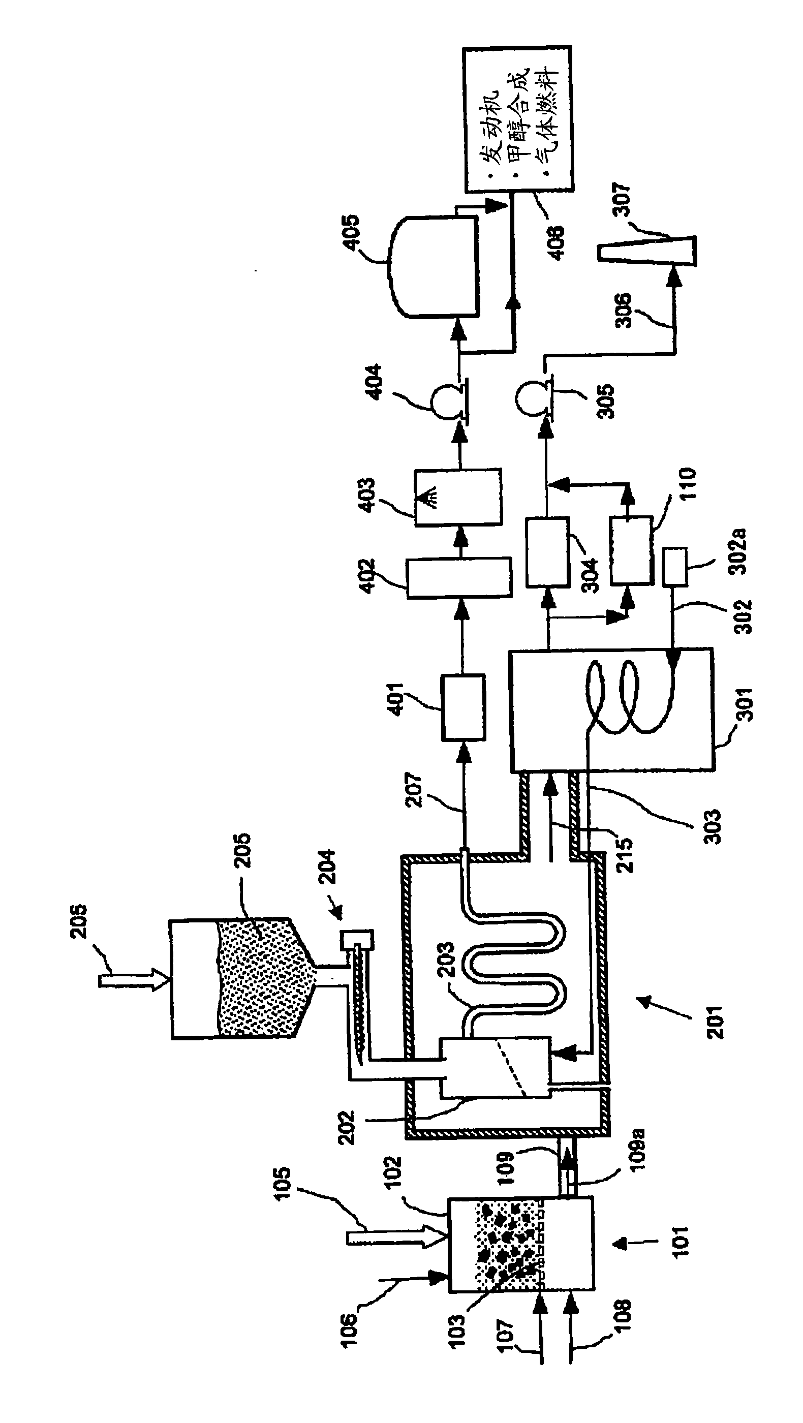
[0071] figure 1 An embodiment of the biomass gasification apparatus of the present invention is shown.

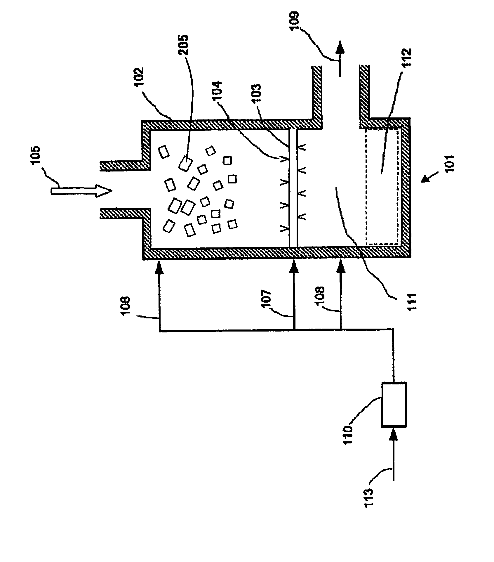
[0072] In the high-temperature combustion gas generator 101, biomass is burned to generate a high-temperature and clean combustion gas (indicated by an arrow) 109a exceeding 900°C. The combustion gas 109a is sent from the combustion gas supply line 109 to the gasification reaction device 201, and heats the primary gasification reaction chamber 202 arranged in the gasification reaction device 201 and the secondary gasification reaction chamber 202 connected to the primary gasification reaction chamber 202 from the outer wall surface. After the gasification reaction tube 203 , the waste gas 215 is formed and discharged from the gasification reaction device 201 .

[0073] The exhaust gas 215 generates superheated steam 303 in the waste heat boiler 301 . The superheated steam 303 is supplied from the gasification agent supply line 302 to the bottom of the primary gasification...

no. 2 Embodiment approach

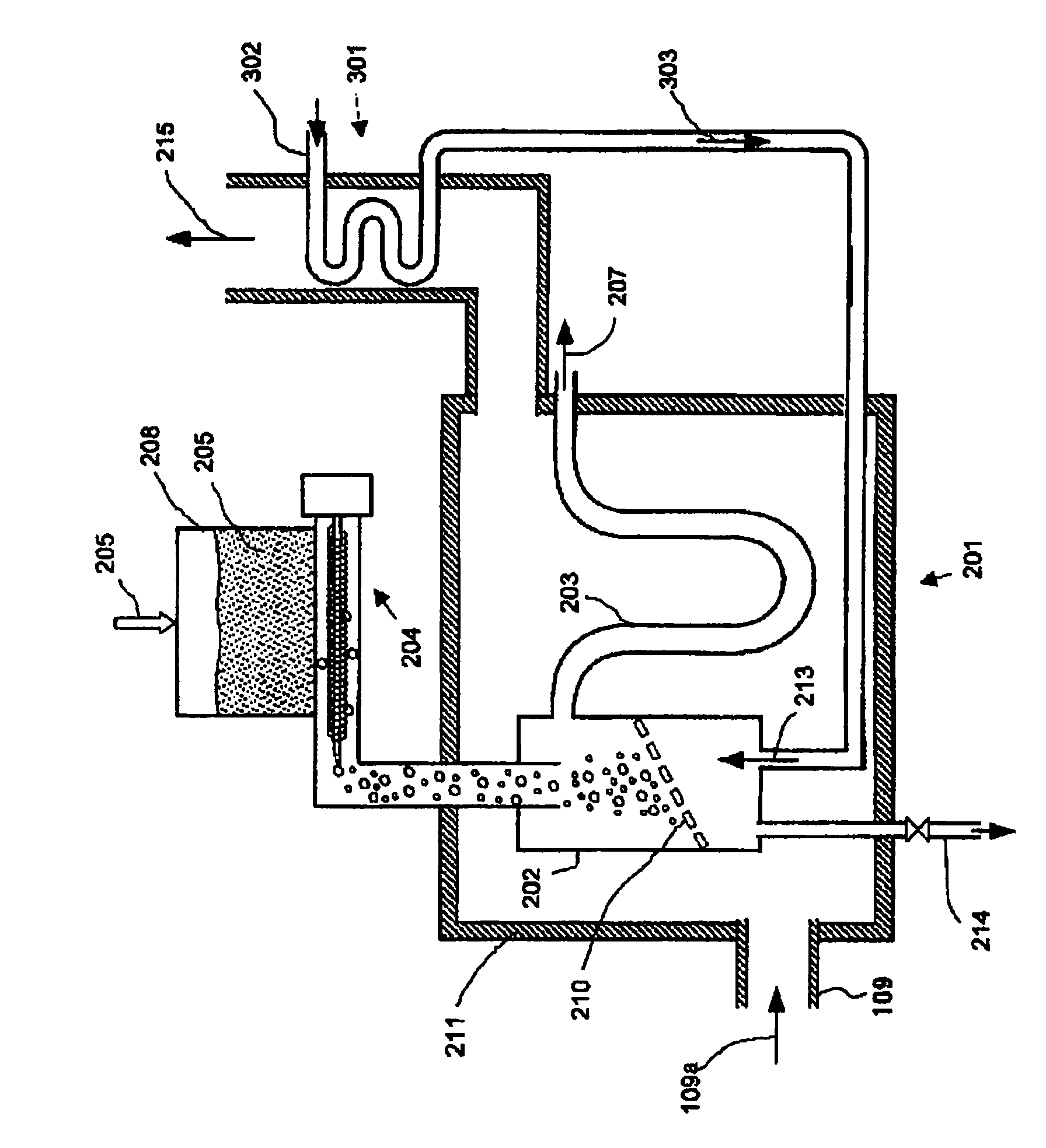
[0100] Figure 5 It is a schematic diagram of a gasification reaction apparatus 201 according to a second embodiment of the present invention provided with a biomass supply hopper 208 and a coarse powder parallel gas supply line 206 .

[0101] In this embodiment, the N 2 , CO 2 , air, or a mixture thereof is sent from the coarse powder parallel gas supply line 206 into the interior of the biomass supply hopper 208 for temporarily storing the coarsely pulverized biomass pieces 205 as the coarse powder parallel gas 206a. Most of the coarse powder parallel gas is dropped and supplied into the primary gasification reaction chamber 202 through the biomass supply line 204 together with the biomass sheet 205 .

[0102] When the coarse powder parallel gas 206 a is not supplied, a large amount of water vapor introduced into the primary gasification reaction chamber 202 through the biomass supply line 204 flows into the biomass supply hopper 208 . Therefore, it is known from experime...

no. 3 Embodiment approach

[0109] Figure 6 It is a schematic diagram of a gasification reactor according to a third embodiment of the present invention further provided with a heat-resistant partition inside.

[0110] In this embodiment, the primary gasification reaction chamber 202 and the secondary gasification reaction tube 203 are separated by a heat-resistant partition wall 212 for the purpose of blocking radiant heat, and the primary gasification reaction chamber 202 forms a The reaction tube 203 is independent of the high temperature chamber 209 of the reaction furnace. The combustion gas generated in the high-temperature combustion gas generating device 101 is sent to the gasification reaction device 201 , and firstly heats the gasification reaction chamber 202 once, and then heats the gasification reaction tube 203 twice. The primary gasification reaction chamber 202 forms a reaction furnace high temperature chamber 209 independent of the secondary gasification reaction tube 203, so the prima...


PUM

PropertyMeasurementUnit
areaaaaaaaaaaa

Abstract

A biomass thermochemical gasification apparatus is provided that can manufacture high-quality fuel gas out of solid biomass in an industrial manner. This fuel gas can be used as fuel for a gas engine and a gas turbine for example and also can be used as synthesis gas for methanol synthesis. A high-temperature combustion gas generation apparatus (101) for biomass operates entirely by biomass and the heat source thereof does not depend on fossil fuel. A coarsely-ground powder biomass (205) subjected to gasification and gasification agent (303) are introduced to a primary gasification reaction room (202) and generate gasification reaction by, as reaction heat, radiation heat from a wall face of the primary gasification reaction room (202) heated by combustion gas (109a) generated in the high-temperature combustion gas generation apparatus (101) and are dissolved. Consequently, the biomass (205) is converted to clean and high-quality generated gas.

Description

technical field [0001] The present invention is related to the gasification technology for converting solid biomass into fuel gas with high convenience, and relates to a gasification reaction device for biomass. The method generates high-quality fuel gas from solid biomass. The high-quality fuel gas is clean and has the same high calorific value as fossil fuels, and can be used as a raw material for chemical synthesis such as methanol. The resulting generated gas can be used as an alternative to fossil fuels, such as gas engine power generation and gas turbine power generation, which are models with high power generation efficiency. It is also used as methanol and GTL (Gas To Liquid fuel; petroleum equivalent fuel) derived from 100% biomass The synthetic gas of the above-mentioned synthetic gas is also used as biodiesel fuel derived from 100% biomass using the above-mentioned synthetic gas. Background technique [0002] Conventional energy conversion of solid biomass mainly...

Claims


Application Information

Patent Timeline
Patent Type & Authority Applications(China)
IPC IPC(8): C10J3/00B09B3/00F23B90/00F23B99/00F23B90/06
CPCY02E50/18C10J3/36Y02E20/18Y02T50/678C10J2300/1665Y02E50/12C10J3/10C10J2300/0956C10J2300/0916C10J3/721C10J2300/1246Y02P20/145Y02P20/129Y02E50/10
Inventor 坂井正康竹川敏之川岛八郎村上信明
Owner NAGASAKI INSTITUTE OF APPLIED SCIENCE
Learn More