L wave band miniature band pass filter with low loss and high suppression

A high suppression and low loss technology, applied in the field of filters, can solve the problems of large volume and insertion loss, limitations, etc., and achieve the effects of low loss, low cost and high reliability in the passband

Inactive Publication Date: 2010-01-06
NANJING UNIV OF SCI & TECH
View PDF0 Cites 29 Cited by
  • Summary
  • Abstract
  • Description
  • Claims
  • Application Information

AI Technical Summary

Problems solved by technology

Conventional filter design methods, such as hairpin filter structures, resonant cavity filter structures, and coaxial line filter structures, have large volume and insertion loss. , handheld wireless terminals, individual mobile communication terminals, etc.) are all subject to great restrictions

Method used


Image

  • L wave band miniature band pass filter with low loss and high suppression
  • L wave band miniature band pass filter with low loss and high suppression
  • L wave band miniature band pass filter with low loss and high suppression

Examples


Embodiment Construction

[0012] The present invention will be described in further detail below in conjunction with the accompanying drawings.

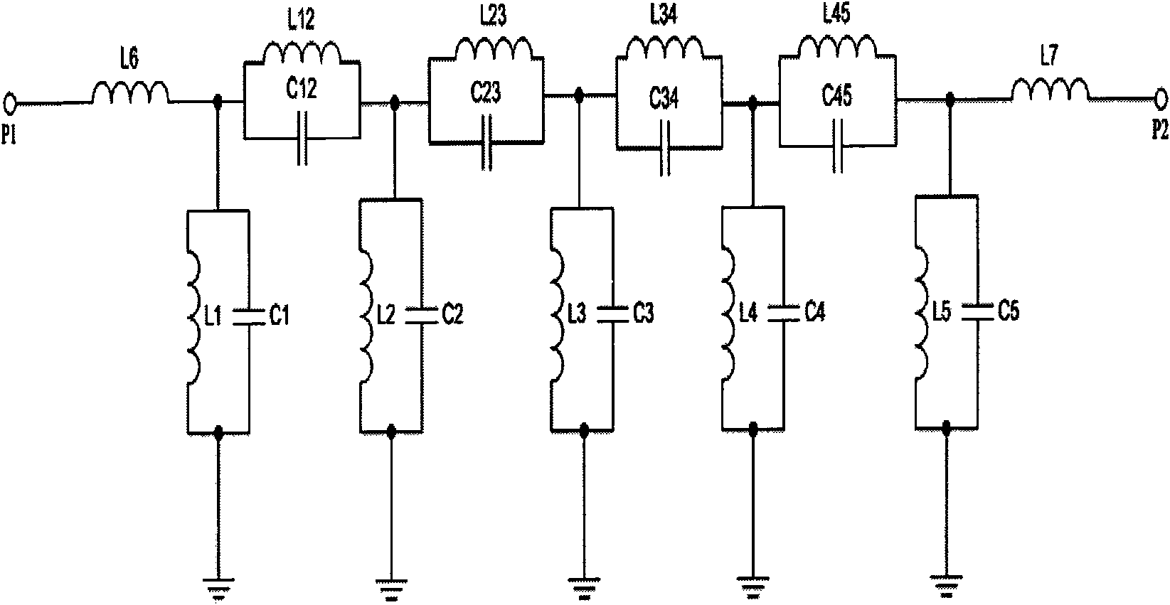
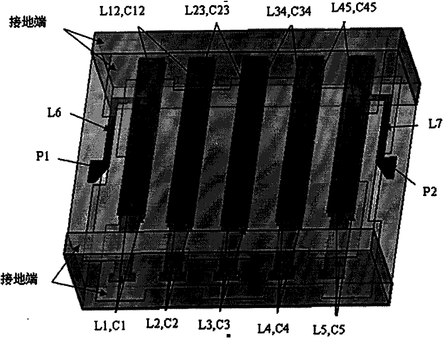
[0013] combine figure 1 , figure 2 , image 3 , a kind of L-band low-loss high-suppression miniature band-pass filter of the present invention, comprises surface-mounted 50 ohm impedance input port P1, input inductance L6, first-stage parallel resonant unit L1, C1, first zero-point setting circuit L12, C12, the second level parallel resonance unit L2, C2, the second zero point setting circuit L23, C23, the third level parallel resonance unit L3, C3, the third zero point setting circuit L34, C34, the fourth level parallel resonance unit L3, C3, the fourth zero-point setting circuit L45, C45, the fifth-stage parallel resonance unit L5, C5, the output inductor L7, the surface-mounted 50-ohm impedance output port P2 and the ground terminal, the input port P1 is connected to the input inductor L6, and the output port P2 is connected to the output inductance L7...


PUM


Abstract

The invention relates to an L wave band miniature band pass filter with low loss and high suppression, which comprises a surface-mounted input/output interface, five parallel resonance units achieved by adopting three layers of folded and coupled strip lines, four zero setting circuits and an input and output inductor, which are all achieved by adopting a multi-layer low temperature co-fired ceramic technology. The invention has the advantages of small volume, light weight, high reliability, excellent electrical performance, good phase-frequency characteristic linearity, good temperature stability, good bulk electrical performance consistency, low cost, mass production and the like, and is particularly suitable for radar, communication, rocket-bearing, airplane-bearing, missile-bearing, spacecrafts, one-man mobile communication terminals and other handheld and portable radio communication terminal products, as well as corresponding band systems which are serious about volume, weight, electrical performance and the like.

Description

technical field [0001] The invention relates to a filter, in particular to an L-band low-loss and high-suppression miniature band-pass filter. Background technique [0002] In microwave and millimeter wave communication, radar and other systems, especially mobile handheld wireless communication terminals, individual satellite mobile communication terminals, military and civilian multi-mode and multi-channel communication system terminals, airborne, missile-borne, and aerospace communication systems, High stop band suppression Miniature microwave intermediate frequency band pass filter is the key electronic component in the receiving and transmitting branches of this band. The main technical indicators describing the performance of this component are: passband operating frequency range, stopband frequency range, passband input / Output voltage standing wave ratio, passband insertion loss, stopband attenuation, shape factor, insertion phase shift and time delay frequency charac...

Claims


Application Information

Patent Timeline
Patent Type & Authority Applications(China)
IPC IPC(8): H01P1/20H01P1/203H03H7/075
Inventor 戴永胜郭玉红叶仲华李宝山王飞宋志东王超宇周文衎肖圣磊姚友芳张杰符光强
Owner NANJING UNIV OF SCI & TECH
Why Eureka
Try Eureka