
Method for connecting target and rear panel through fusion welding

A distributed and backplane technology, applied in welding equipment, laser welding equipment, electron beam welding equipment, etc., can solve problems such as complex process, difficult processing, complex process realization, etc.

Active Publication Date: 2010-03-17
GRIKIN ADVANCED MATERIALS
View PDF0 Cites 3 Cited by
  • Summary
  • Abstract
  • Description
  • Claims
  • Application Information

AI Technical Summary

Problems solved by technology

For example, the surface of the target and the backplane can be processed into a structure that can be locked or occluded with each other, and the reliable connection between the target and the backplane is achieved through mechanical cooperation. The connection process of this method is relatively simple, but the target and the backplane The matching structure that needs to be processed on the surface is complex and difficult to process. At the same time, the positioning accuracy of the target and the back plate is high.
Another typical method is to realize the connection between the target and the backplane through large pressure extrusion and subsequent long-term thermal diffusion treatment process at a certain temperature. This method is more complicated and less efficient.
Therefore, although the above-mentioned connection method between the target and the back plate is feasible for the processing and preparation of target components, the process implementation is relatively complicated.

Method used


Image

  • Method for connecting target and rear panel through fusion welding
  • Method for connecting target and rear panel through fusion welding
  • Method for connecting target and rear panel through fusion welding

Examples


Embodiment 1

[0022] Connection of high-purity Al-0.5% Cu (wt.) alloy (purity > 99.9995%) circular target and 6061Al alloy back plate. The connection process is as follows:

[0023] 1. The 6061Al alloy back plate is shot peened to roughen the surface;

[0024] 2. Stack the Al-0.5% Cu alloy target and the 6061Al alloy back plate in the center, heat to 200-280 ° C, apply a pressure of 50-150 MPa under the press, and press the two surfaces to be connected without gaps Together;

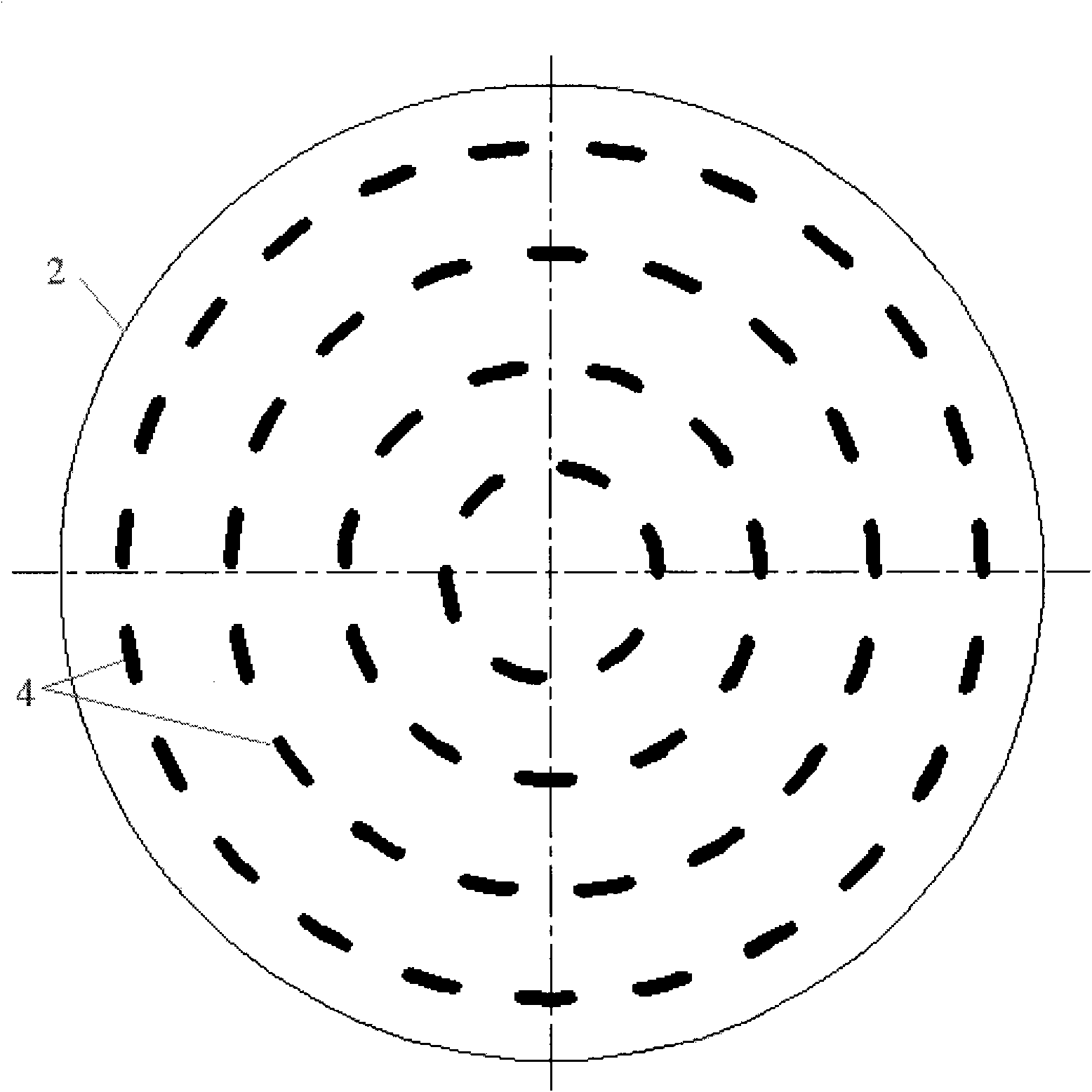
[0025] 3. Lay the pressed target and back plate components flat, and use electron beams to carry out distributed deep penetration welding from the surface of the 6061Al back plate. The interface bonding method between the back plate and the target is as follows: figure 1 shown. During welding, the start and end of welding are realized by controlling the opening and closing of the electron beam. The length of each bead is about 10mm, forming a non-continuous concentric bead array with the center of the back plate (t...

Embodiment 2

[0029] Welding of high-purity Al-4% Cu (wt.) alloy (purity > 99.999%) rectangular target and 2024Al alloy back plate. The connection process is as follows:

[0030] 1. The Al-4% Cu and 2024Al alloy backplanes are milled to roughen their surfaces;

[0031] 2. Stack the Al-4% Cu alloy target and the 2024Al alloy back plate together, heat them to 250-350°C, press the two surfaces to be connected together without gaps under a press with a pressure of 120-200MPa Together;

[0032] 3. Lay the pressed target material and the back plate assembly flat, and use the laser beam to conduct distributed deep penetration welding from the surface of the 2024Al back plate. During welding, the laser beam is controlled to turn on and off the light. The time of each welding pass about 15mm in length, formed as Figure 4 The discontinuous bead distribution pattern shown. The welding depth is controlled by adjusting the output power of the laser beam, scanning speed, etc., and the back plate and...


PUM


Abstract

The invention belongs to a method for connecting a target and a rear panel through fusion welding, which comprises the following steps of: firstly, coarsening at least one surface to be connected of the target and the rear panel; secondly, pressing the target and the rear panel together; and finally, performing distributive penetration fusion welding from the surface of the rear panel with high energy beams, such as electronic beams and laser beams so as to weld the rear panel and target component together. The method utilizes the characteristics of the high energy beams of intensive energy density, good controllability, high depth-to-width ratio of welding lines and the like, and can directly and thoroughly weld the rear panel; and the welding lines which are formed by welding the rear panel and the target material have high bonding strength and small heat affected zone. In a distributed discontinuous welding mode, the method solves the problems such as growth of crystalline grains caused by suddenly raised target material temperature because of too large input amount of the welding heat and deformation caused by high welding heat stress. The method is a simple and reliable methodfor connecting the target and the rear panel because of low requirements on processing of the target and the rear panel, short welding time and high bonding strength, and is suitable for the preparation of sputtering targets.

Description

technical field [0001] The invention relates to a method for connecting a target and a back plate, which is applied to the preparation of sputtering target components. Background technique [0002] The connection between the target and the backplane is the key technology for the preparation of PVD sputtering target components for semiconductor integrated circuits, liquid crystal display and other industries. In addition to meeting the requirements of good thermal conductivity, electrical conductivity and bonding strength, the connection between the target and the backplane must also ensure that the connection process does not affect the chemical purity and tissue properties of the target. [0003] High-purity aluminum, aluminum alloys, and high-purity copper are widely used sputtering target materials, and ordinary aluminum and copper alloys are common backplane materials. Currently, various methods exist for attaching these targets to the backplane. For example, the surfa...

Claims


Application Information

Patent Timeline
Patent Type & Authority Applications(China)
IPC IPC(8): C23C14/34B23K15/00B23K26/20B23K26/24
Inventor 何金江江轩熊晓东王欣平杨亚卓廖赞尚再艳
Owner GRIKIN ADVANCED MATERIALS
Learn More