Method for electrically restoring soil and underground water

A groundwater electric and repair method technology, applied in the direction of chemical instruments and methods, restoration of polluted soil, water pollutants, etc., can solve problems such as low current efficiency, low current efficiency, electrode corrosion, and unstable effect, and achieve current The effect of improving efficiency and eliminating potential safety hazards

Inactive Publication Date: 2010-04-28
CHONGQING UNIV
View PDF0 Cites 25 Cited by
  • Summary
  • Abstract
  • Description
  • Claims
  • Application Information

AI Technical Summary

Problems solved by technology

At present, the electrodes used in electric repair technology are corrosion-resistant and anti-oxidation inert electrodes. The working fluid is mainly alkali metal salts such as KCl. During the repairing process, water is electrolyzed to generate hydrogen ions or hydroxide ions, releasing O 2 、H 2 or Cl 2 gas, which causes soil and groundwater acidification while removing pollutants from the soil and groundwater
During the repair process, due to the H + ions and OH - The electromigration speed of ions is much higher than that of other ions, so that the actual current used for pollutant migration accounts for less than 1% of the total current, and the current efficiency is extremely low. At the same time, it also limits the improvement of the repair voltage, making the repair time as long as possible. Months or even years, the effect is unstable
Soil and groundwater acidification, extremely low current efficiency, and electrode corrosion issues severely restrict the widespread use of this technology

Method used


Image

  • Method for electrically restoring soil and underground water
  • Method for electrically restoring soil and underground water
  • Method for electrically restoring soil and underground water

Examples


Embodiment Construction

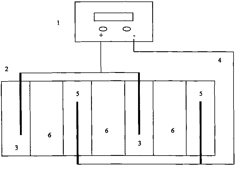
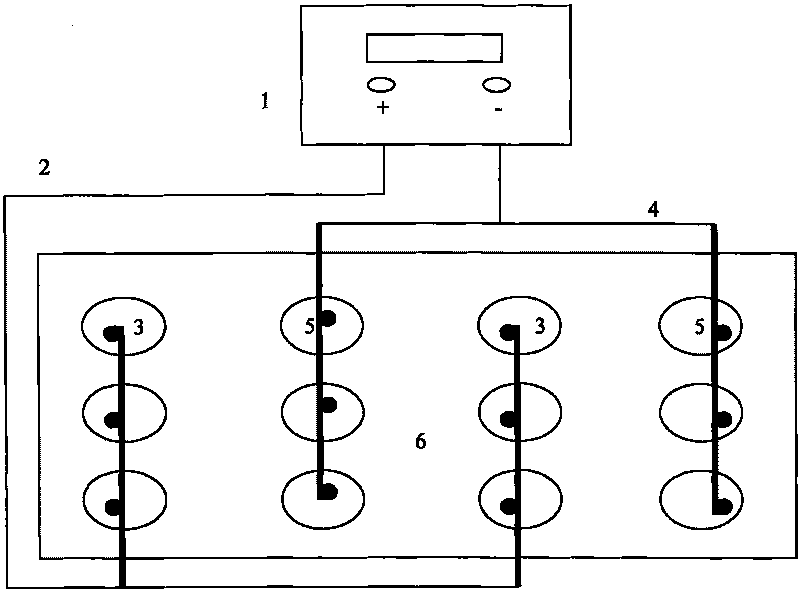
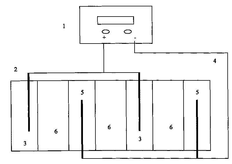
[0016] see figure 1 with figure 2 , the disinfection device consists of 3 parts:

[0017] (1) Power supply 1. The power supply can adopt DC power supply or DC pulse power supply to supply power to the electrodes.

[0018] (2) Anode electrode 2 , cathode electrode 4 , anode reaction cell 3 and cathode reaction cell 5 . The anode reaction pool 3 and the cathode reaction pool 5 are located at both ends of the repaired soil and groundwater 6, and the anode electrode 2 and the cathode electrode 4 are inserted in the anode reaction pool 3 and the cathode reaction pool 5;

[0019] (3) Soil and groundwater that need remediation6.

[0020] The above two figures are only schematic diagrams of the working principle, and the specific arrangement of electrodes and electrode reaction cells is not limited to these two ways.

[0021] The anode working fluid is ferric chloride solution with a concentration of 0.05M, the cathode working fluid is a copper sulfate solution with a concentrat...


PUM


Abstract

The invention provides a method for electrically restoring soil and underground water, which is realized in a way that: soil or underground water which needs to be restored is used as the conducting medium, metallic iron is used as the anode, a ferric salt solution is used as the working solution, the anode iron is oxidized into ions after losing electrons, the ions enter the anode working solution and move towards the cathode into the soil or underground water as the current carrier with positive charges under the action of an electric field; and copper or copper-coated iron or iron is used as the cathode, a cupric salt or ferric salt solution is used as the working solution, cupric ions or trivalent ferric ions are reduced into elementary substance copper or bivalent ferric ions, meanwhile, small amounts of heavy metal cations transferring from the soil to the cathode working liquid are also reduced, and acid radicals of cupric salts or ferric salts move towards the anode under the action of the electric field and enter the soil and the underground water. The method can restore soil and underground water which are polluted by heavy metals, acids or alkalis, does not change the pH value of the soil and the underground water, does not produce hydrogen, oxygen or chlorine with hidden danger and has the advantages of high current efficiency, low price and easy obtainment of the anode material.

Description

technical field [0001] The invention relates to an electric restoration technology for polluted soil and underground water. Background technique [0002] When the waste water and solid waste generated in the industrial production process enter the soil, it will lead to soil and groundwater pollution. When the site is changed to residential, agricultural and other purposes with strict soil quality requirements, soil and groundwater restoration must be carried out. , to remove pollutants from soil and groundwater. [0003] The main methods of soil and groundwater remediation are: (1) physical remediation: physical separation remediation, curing / stabilization remediation, steam leaching remediation, electric (electrochemical) remediation; (2) chemical remediation: chemical leaching remediation, solvent leaching (3) Bioremediation: prepared bed method, soil composting method, mud bioreactor method, land cultivation method. [0004] Among them, the electric repair technology us...

Claims


Application Information

Patent Timeline
Patent Type & Authority Applications(China)
IPC IPC(8): C02F1/461C02F1/62B09C1/08C02F101/20
Inventor 李东
Owner CHONGQING UNIV
Why Eureka
Try Eureka