
Purification system for flue gas generated by burning wastes and purification process thereof

A technology of incineration flue gas and purification system, applied in chemical instruments and methods, separation of dispersed particles, combined devices, etc., can solve the problems of occupying land resources, high cost of stabilizers, easy precipitation of heavy metals, etc.

Inactive Publication Date: 2010-08-25
瀚蓝(厦门)固废处理有限公司 +2
View PDF0 Cites 36 Cited by
  • Summary
  • Abstract
  • Description
  • Claims
  • Application Information

AI Technical Summary

Problems solved by technology

Among them, the main problems of melting and sintering are large energy consumption, high tail gas treatment costs and high operating costs; the solidification method is a process of mixing and containing fly ash in inert materials by physical and chemical methods to stabilize it, and its main disadvantages It cannot fundamentally solve the problem of dioxins in fly ash, some heavy metals are easy to precipitate, and increase the final disposal amount of hazardous waste. The stabilization treatment method is to add an appropriate amount of heavy metal stabilizer to fly ash, and fully Insoluble compounds are formed after mixing, the main problem with this method is the high cost of stabilizers, resulting in higher fly ash disposal costs, and the generation of waste water with high concentrations of inorganic salts that needs to be treated
[0020] Generally, safe landfill after solidification and stabilization is the final way of fly ash disposal, which occupies a large amount of land resources and has a long-term impact on the environment

Method used


Image

  • Purification system for flue gas generated by burning wastes and purification process thereof
  • Purification system for flue gas generated by burning wastes and purification process thereof
  • Purification system for flue gas generated by burning wastes and purification process thereof

Examples


Embodiment Construction

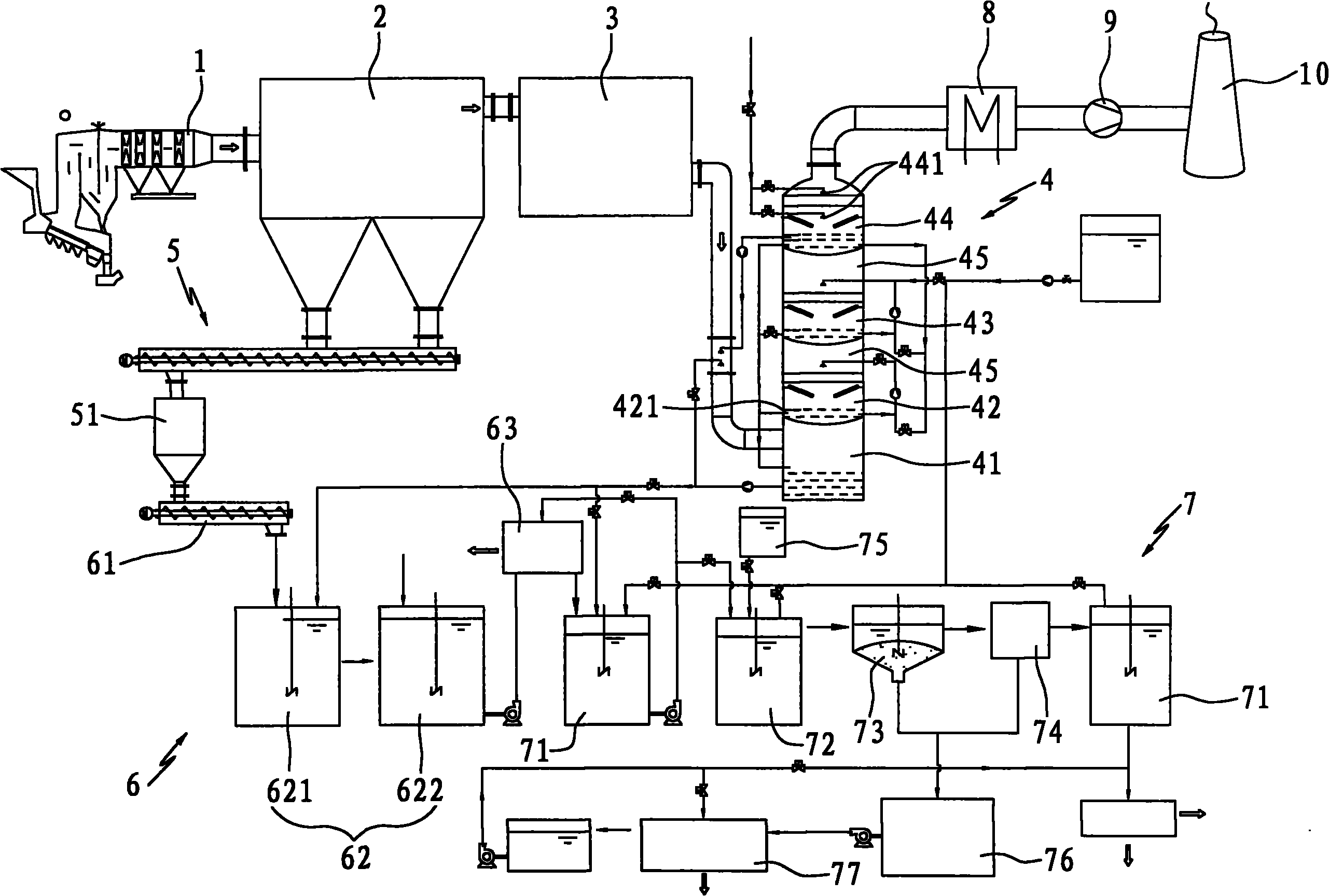
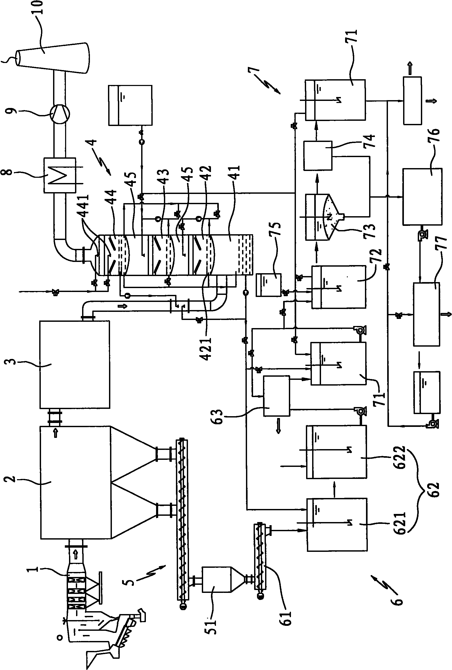
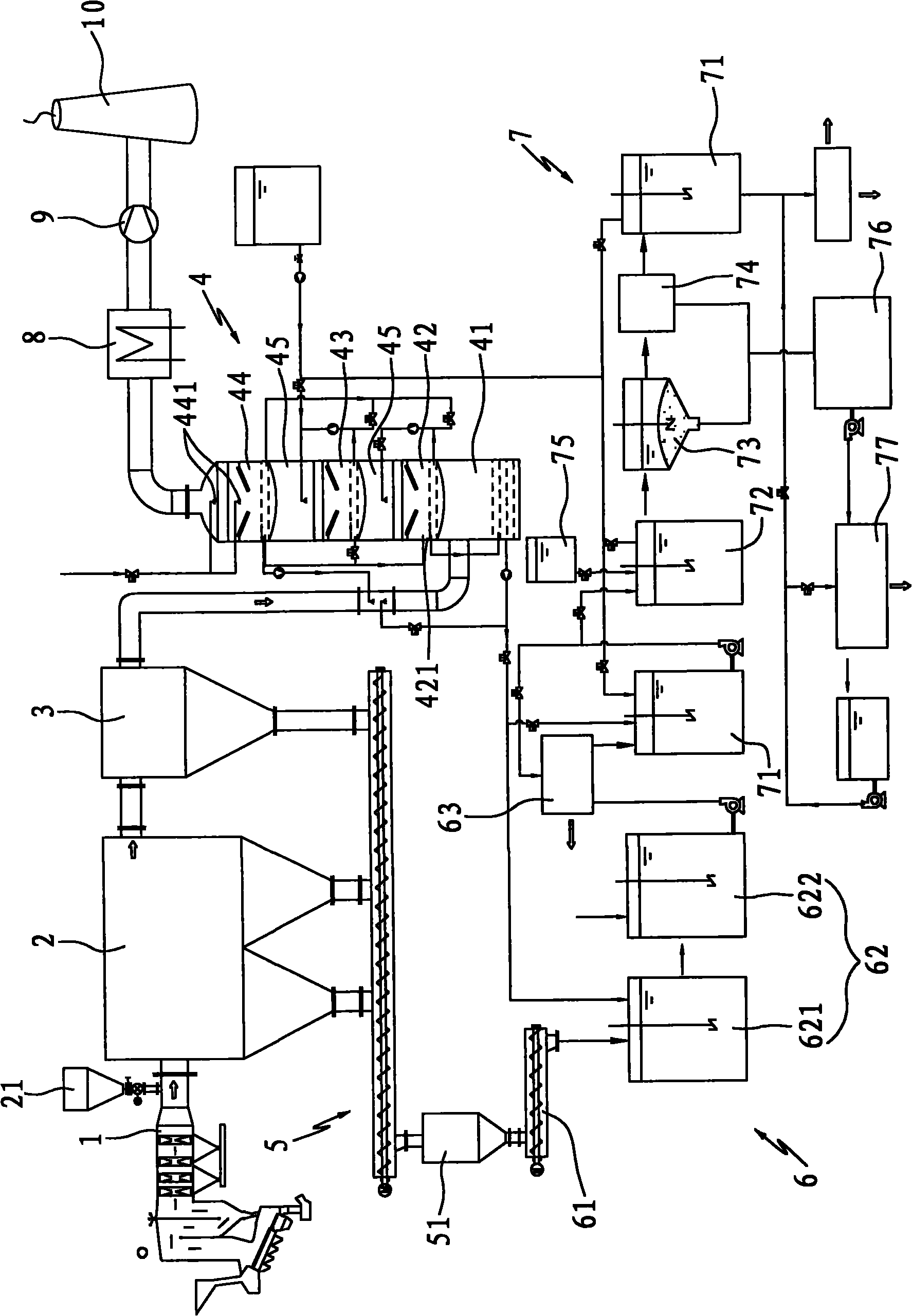
[0053] As shown in Figures 1 and 2, a waste incineration flue gas purification system disclosed by the present invention is arranged between the outlet of the waste incineration (waste heat) boiler and the chimney 10, including the flue 1 of the waste incinerator and the dust collector 2 , Independent dioxin removal device 3, flue gas scrubber 4, fly ash collection device 5, fly ash washing and dehydration system 6, sewage treatment system 7, flue gas heating device 8 and induced draft fan 9.

[0054] One side of the upper part of the dust collector 2 is connected to the flue 1, the other side is connected to the dioxin decomposition and removal device 3, and the bottom of the dust collector 2 is connected to the fly ash collection device 5; the fly ash collection device 5 is connected to the fly ash washing and dehydration system 6, and the The sump at the bottom of the gas scrubber is connected to the fly ash washing and dehydration system; the dioxin decomposition and remova...


PUM


Abstract

The invention discloses a purification system for flue gas generated by burning wastes and a purification process thereof. The purification system comprises a flue of a refuge incinerator, a dust remover, a device for decomposing and removing dioxins, a flue gas washing tower, a fly ash collecting device, a fly ash washing and dehydrating system, a sewage treatment system, a flue gas heating device and a draught fan; one side of an inlet of the dust remover is connected with the flue, and the other side of the inlet of the dust remover is connected with the device for decomposing and removing dioxins; the fly ash collecting device is connected under the dust remover and the fly ash washing and dehydrating system; the device for decomposing and removing dioxins is connected with the lower part of the flue gas washing tower through a pipeline; an outlet of the flue gas washing tower is connected with the flue gas heating device; meanwhile, a water drain of the flue gas heating device is respectively connected with the fly ash washing and dehydrating system and the sewage treatment system; and purified flue gas is exhausted through the draught fan by using the flue gas heating device. The flue gas can meet the stricter exhaust standard by the purification treatment processes of removing dust, decomposing the dioxins, absorbing and neutralizing acid gases, removing heavy metals, deeply removing dust and the like.

Description

technical field [0001] The invention relates to a purification technology for flue gas produced by incineration of wastes such as general domestic waste, medical waste, hazardous waste and industrial waste, in particular to a waste incineration flue gas purification system and its purification process. Background technique [0002] With the process of urbanization and the development of industry and medical and health services, the treatment and disposal of various wastes has attracted more and more attention. As one of the most effective means of disposing of waste, waste incineration has been widely used. [0003] Since garbage is a mixture with relatively complex components, which contains some organic compounds, chlorides, sulfides, fluorides, etc., and also contains a large amount of heavy metals, according to relevant data, the content of chromium is generally 100-450g / t, nickel 50-200g / t copper, 450-2500g / t copper, 900-3500g / t zinc, 750-2500g / t lead, 10-40g / t cadmium...

Claims


Application Information

Patent Timeline
IPC IPC(8): B01D53/74B01D53/78B01D53/86B01D53/72B01D53/68B01D53/50B01D50/00
Inventor 屠柏锐林岩赖剑波脱培德闵泽清陆海王占全
Owner 瀚蓝(厦门)固废处理有限公司
Learn More