
Glove box protective argon arc welding method

A glove box and argon arc welding technology, applied in arc welding equipment, welding equipment, manufacturing tools, etc., can solve the problems of no uniform standard for argon arc welding process parameters, low qualified rate of welding finished products, and inability to weld in batches, etc., to achieve Improved anti-oxidation effect, high welding efficiency, and improved quality

Inactive Publication Date: 2010-09-29
NANJING SANLE ELECTRONICS INFORMATION IND GRP
View PDF3 Cites 15 Cited by
  • Summary
  • Abstract
  • Description
  • Claims
  • Application Information

AI Technical Summary

Problems solved by technology

[0002] Welding technology is widely used in the production of mechanical equipment. Ordinary welding technology uses high current to melt the welding material and integrate the separated metal materials. However, because the ordinary welding technology is carried out in the air, the welding material is easily absorbed by the air. Oxygen oxidation, poor performance of welding products such as pressure resistance
Argon arc welding welding technology is based on the principle of ordinary arc welding, using argon or nitrogen to protect the metal welding material, through high current to make the welding material melt into a liquid state on the base material to be welded to form a molten pool, so that the welded material A welding technology that achieves metallurgical bonding between metals. Due to the continuous feeding of protective gases such as argon or nitrogen during high-temperature fusion welding, the metal to be welded cannot be in contact with oxygen in the air, thereby preventing the metal to be welded from being oxidized. However, this isolation is protected by airflow, which cannot completely isolate oxygen from the metal to be welded. Oxidation is easy to occur when welding easily oxidized metals such as copper, nickel, and stainless steel, and there is no uniform standard for the current argon arc welding process parameters. It cannot be welded in batches, the welding efficiency is low, the qualified rate of welded products is low, and it cannot meet the high standard

Method used


Image

  • Glove box protective argon arc welding method
  • Glove box protective argon arc welding method

Examples


Embodiment 1

[0024] A glove box protected argon arc welding method, specifically comprising the following steps:

[0025] (1) Turn on the power, open the argon valve in the pipeline, turn on the micro oxygen meter and dew point meter, press the cleaning button, wait until the oxygen content reaches 50PPM, and the water content reaches -50, turn off the cleaning button, open the cycle button, and enter the dehydration and dewatering oxygen state;

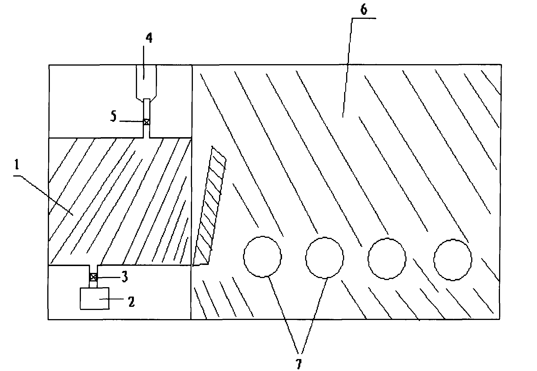
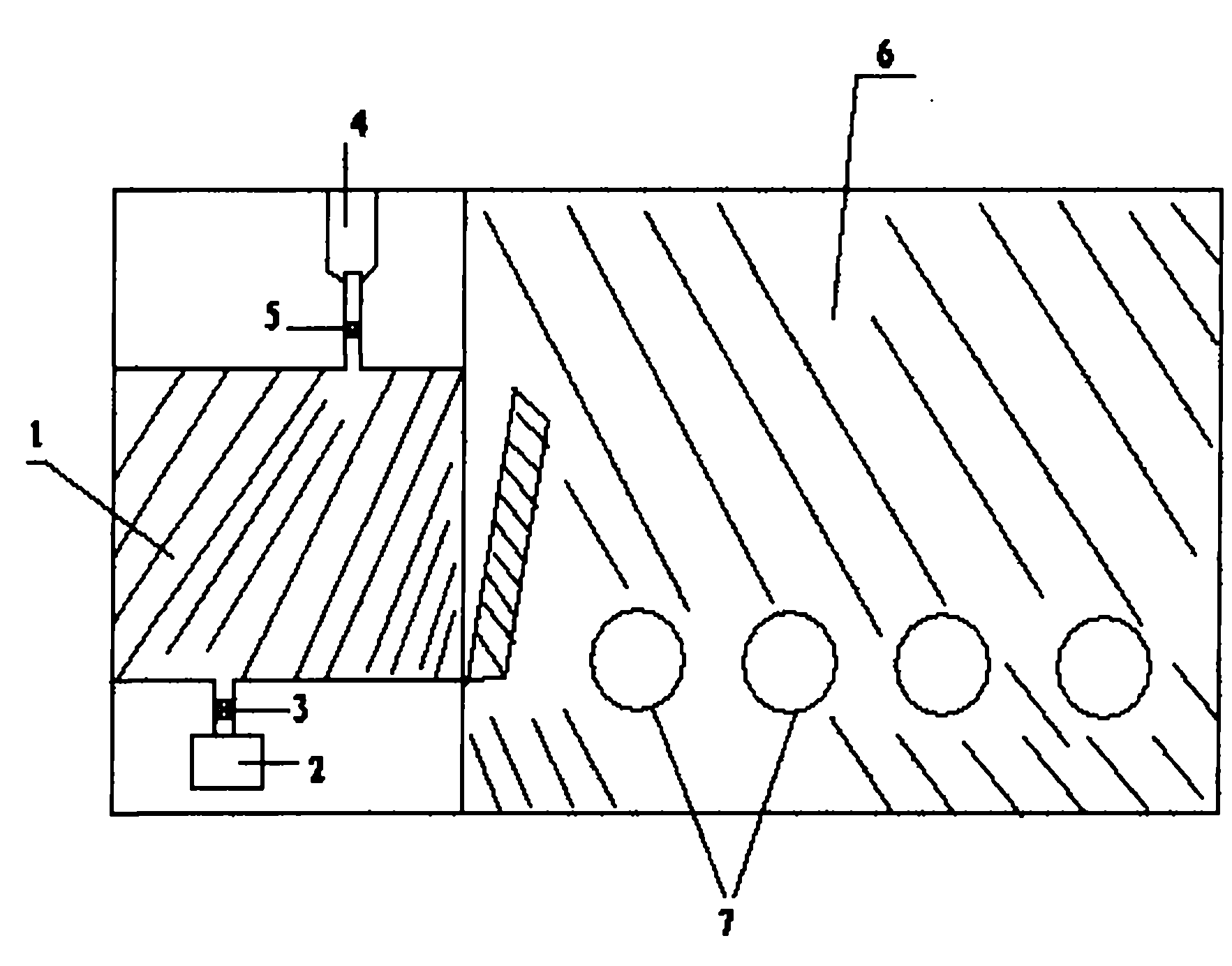
[0026] (2) Open the outer door of the transition chamber (1), place the workpiece to be welded on the stage of the transition chamber (1), close the outer door of the transition chamber (1), and open the exhaust valve (3) of the vacuum pump (2). Vacuum until the pressure gauge reaches zero, close the pumping valve (3), open the inflation valve (5) of the argon cylinder (4), and fill the transition chamber (1) and glove box (6) with argon until the pressure gauge is full , close the inflation valve (5), open the exhaust valve (3) again to evacuat...

Embodiment 2

[0030] A glove box protected argon arc welding method, specifically comprising the following steps:

[0031] (1) Turn on the power, open the argon valve in the pipeline, turn on the micro oxygen meter and dew point meter, press the cleaning button, wait until the oxygen content reaches 10PPM, and the water content enters -60, turn off the cleaning button, open the cycle button, and enter the dehydration and dewatering oxygen state;

[0032] (2) Open the outer door of the transition chamber (1), place the workpiece to be welded on the stage of the transition chamber (1), close the outer door of the transition chamber (1), and open the exhaust valve (3) of the vacuum pump (2). Vacuum until the pressure gauge reaches zero, close the pumping valve (3), open the inflation valve (5) of the argon cylinder (4), and fill the transition chamber (1) and glove box (6) with argon until the pressure gauge is full , close the inflation valve (5), open the exhaust valve (3) again to evacuate t...

Embodiment 3

[0036] A glove box protected argon arc welding method, specifically comprising the following steps:

[0037] (1) Turn on the power, open the nitrogen valve of the pipeline, turn on the micro oxygen meter and dew point meter, press the cleaning button, wait until the oxygen content reaches 20PPM, and the water content enters -40, turn off the cleaning button, open the cycle button, and enter the water removal and oxygen removal state;

[0038] (2) Open the outer door of the transition chamber (1), place the workpiece to be welded on the stage of the transition chamber (1), close the outer door of the transition chamber (1), and open the exhaust valve (3) of the vacuum pump (2). Vacuum until the pressure gauge reaches zero, close the pumping valve (3), open the inflation valve (5) of the argon gas cylinder (4), and fill the transition chamber (1) and the glove box (6) with nitrogen until the pressure gauge is full. Close the inflation valve (5), open the exhaust valve (3) again...


PUM


Abstract

The invention discloses a glove box protective argon arc welding method. In the method, the oxygen concentration in a transition cabin and a glove box of the glove box protective argon arc welding equipment is lowered to minimum through the method of rapid vacuum pumping, aerating, rapid vacuum pumping and secondary aerating by the glove box protective argon arc welding equipment, and the factors, such as protective gas, protective gas flow, welding current, arc length and welding speed and the like in the welding process are screened to determine best welding process. Experimental results indicate that the glove box protective argon arc welding method provided by the invention can further improve anti-oxidation effect, has high welding efficiency and good-quality welded products, and can be used on high-power products; if the method is used for high-power travelling wave tubes, the quality of the travelling wave tubes is improved, the service life is prolonged and the economic benefit is better.

Description

technical field [0001] The invention designs a welding method, and in particular relates to a glove box protection and anti-oxidation argon arc welding method. Background technique [0002] Welding technology is widely used in the production of mechanical equipment. Ordinary welding technology uses high current to melt the welding material and integrate the separated metal materials. However, because the ordinary welding technology is carried out in the air, the welding material is easily absorbed by the air. Oxygen oxidation, welding products have poor performance such as pressure resistance. Argon arc welding welding technology is based on the principle of ordinary arc welding, using argon or nitrogen to protect the metal welding material, through high current to make the welding material melt into a liquid state on the base material to be welded to form a molten pool, so that the welded material A welding technology that achieves metallurgical bonding between metals. Due...

Claims


Application Information

Patent Timeline
IPC IPC(8): B23K9/167B23K9/095B23K9/23B23K9/235
Inventor 董笑瑜张浩赵刚周培章
Owner NANJING SANLE ELECTRONICS INFORMATION IND GRP
Learn More