Low-temperature thermocompression bonding method

A thermocompression bonding, low temperature technology, applied in the manufacture of electrical components, circuits, semiconductor/solid-state devices, etc., can solve the problems of high temperature and high pressure, achieve convenient operation, reduce thermal stress and thermal deformation, and simple process. Effect

Active Publication Date: 2010-10-06
HUAZHONG UNIV OF SCI & TECH
View PDF4 Cites 17 Cited by
  • Summary
  • Abstract
  • Description
  • Claims
  • Application Information

AI Technical Summary

Problems solved by technology

For the existing thermocompression bonding technology, the main problems are

Method used


Image

  • Low-temperature thermocompression bonding method
  • Low-temperature thermocompression bonding method
  • Low-temperature thermocompression bonding method

Examples


Embodiment 1

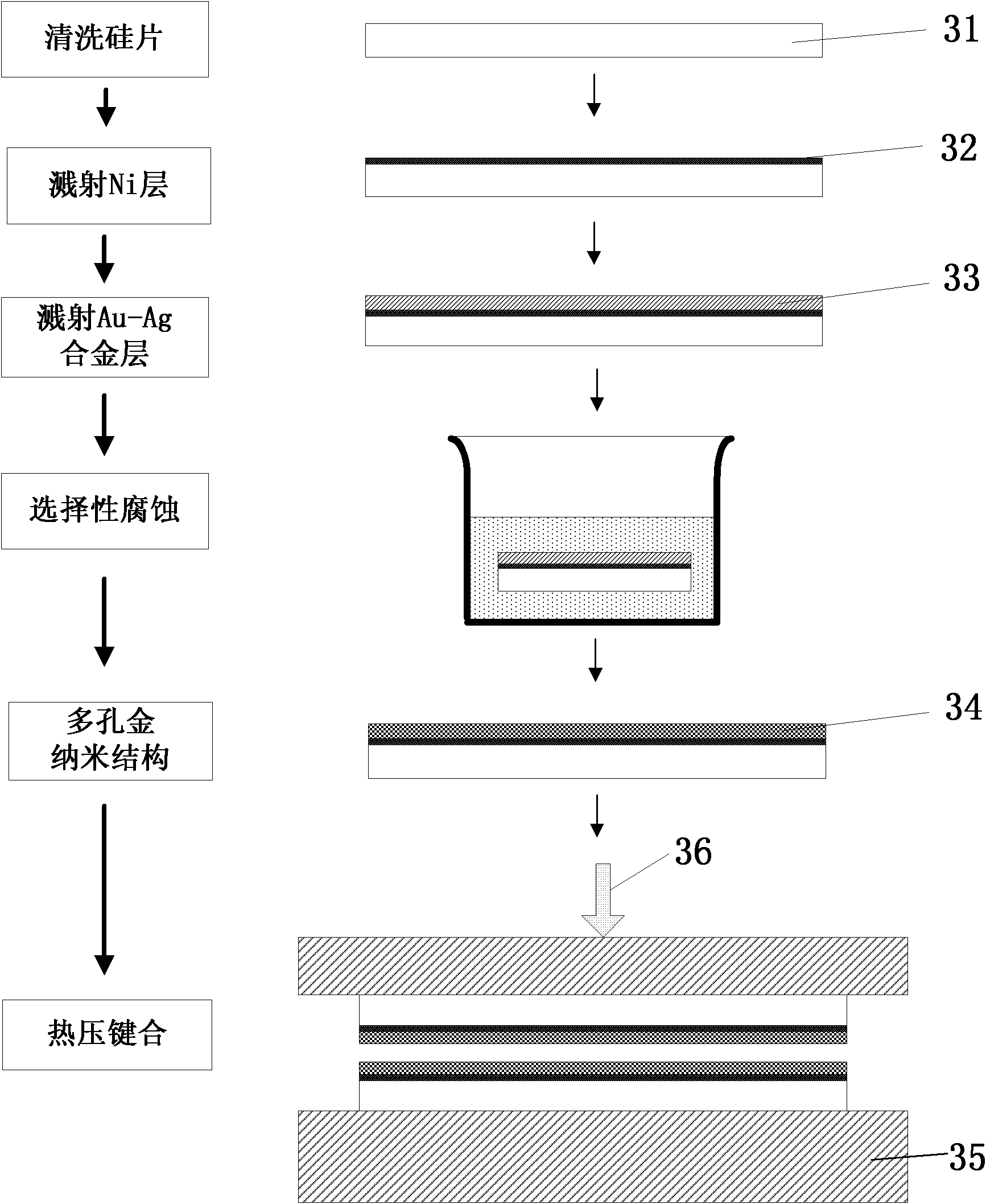
[0020] 1. Use standard RCA process to clean silicon wafer 31, and then deposit Ni layer 32 (30nm) and Au-Ag alloy layer 33 (3μm) on the silicon wafer through sputtering process;

[0021] 2. Put the silicon wafer into 75% HNO 3 In the solution, etch at room temperature for 20 minutes to etch the Ag in the Au-Ag alloy, then wash with deionized water and dry with nitrogen to obtain a porous gold nanostructure layer 34 with a hole size of 20-30 nm on the surface of the silicon wafer;

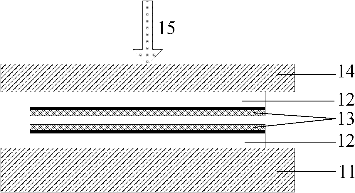
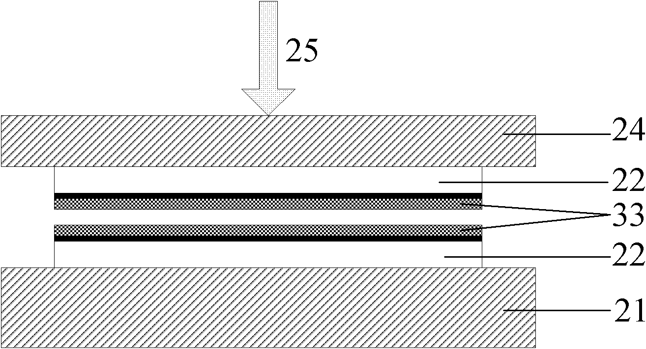
[0022] 3. Place the two silicon wafers with the porous gold nanostructure layer 34 face to face on the hot plate 35, raise the temperature of the hot plate to 150°C, and then apply a pressure of 1 MPa, heat preservation and pressure for 30 minutes, to complete the thermocompression bonding.

Embodiment 2

[0024] The process flow of this embodiment is basically the same as that of embodiment 1, except that the alloy layer is changed to a Cu-Al alloy, and a 5% HCl solution is used for corrosion. The bonding temperature is 220°C and the pressure is 5MPa.

Embodiment 3

[0026] 1. Clean the glass sheet 41, and then deposit the Ni layer 42 (30nm) and Cu layer 43 (1μm) on the glass surface through a sputtering process;

[0027] 2. Put the glass sheet with the Cu layer sputtered in a 5% HCl solution for 1 minute to remove surface oxides, then rinse with deionized water, and then put it in the ammonium chloride zinc plating solution. The Zn layer 44 is electroplated on the layer, and the electroplating time is 10 minutes. After electroplating, the glass sheet was cleaned with deionized water, dried with nitrogen, and then placed in an annealing furnace for heat treatment. The annealing temperature was 150°C and the holding time was 2h. The metal Zn and Cu were atomically diffused to obtain Cu- with a thickness of 5μm. Zn alloy layer 45;

[0028] 3. Put the glass sheet with the Cu-Zn alloy layer into 8% NaOH solution and etch for 10 hours to corrode the Zn in the Cu-Zn alloy, then clean it with deionized water and dry it with nitrogen to obtain a hole ...


PUM

PropertyMeasurementUnit
Thicknessaaaaaaaaaa
Sizeaaaaaaaaaa
Hole sizeaaaaaaaaaa

Abstract

The invention provides a low-temperature thermocompression bonding method, in which a layer of alloy film is manufactured on a substrate, and then a part of components in the alloy is removed via a selective etching technique so as to change the alloy film into a layer of a porous nano-structure. The porous nano-structure is used as a bonding layer, and thermocompression bonding can be realized at lower temperature and pressure due to the nano-scale effect. The invention has simple technology, is operated simply, obviously reduces thermal stress and thermal deformation in the bonding process at lower temperature and pressure, and is widely used in the fields of optoelectronic integration, three-dimensional packaging, system packaging and the like.

Description

Technical field [0001] The invention belongs to the field of electronic manufacturing, and particularly relates to a low-temperature thermal compression bonding method. Background technique [0002] With the requirements of high integration and multi-functionality of microelectronic devices, the existing 2D packaging technology is difficult to meet the requirements, while the three-dimensional packaging and system-in-package have small size and light weight. The length of the interconnection line is shortened to reduce signal delay and improve Advantages such as efficiency are becoming the mainstream technology of electronic packaging. Bonding is a key process for realizing three-dimensional packaging and a bottleneck restricting the development of three-dimensional packaging technology. The bonding technologies currently applied to three-dimensional packaging can be roughly divided into two categories: one is direct bonding technology without an intermediate layer, which mainly...

Claims


Application Information

Patent Timeline
IPC IPC(8): H01L21/603H01L21/3213
Inventor 陈明祥蔡明先彭聪刘胜
Owner HUAZHONG UNIV OF SCI & TECH
Why Eureka
Try Eureka