Independent heat tube energy-saving heating/heat exchange system special for spray coating/spray lacquer production line

A heat exchange system and production line technology, applied in indirect heat exchangers, lighting and heating equipment, coatings, etc., can solve the problem of low heat exchange utilization rate of heat exchangers, low heat exchange efficiency of heat exchangers, and thermal conductivity of stainless steel Low-level problems, to achieve good heat transfer/heat conduction characteristics, speed up heat transfer speed, and short heat transfer time

Inactive Publication Date: 2010-10-20
宁波福威克能源科技有限公司
View PDF0 Cites 7 Cited by
  • Summary
  • Abstract
  • Description
  • Claims
  • Application Information

AI Technical Summary

Problems solved by technology

[0007] The heat exchanger in the drying heating / heat exchange system of the fourth coal-fired heating tube type (fossil coal-fired coke) and the heat exchange in the drying heating / heat exchange system of the fuel-fired heating tube type (light diesel oil) The difference is that it uses a coal-fired hot blast stove. The high-temperature flue gas (800-600°C) generated by the combustion of fuel coal in the furnace of the coal-fired hot blast stove enters the pyrotechnic tube, and passes through the stainless steel heat exchanger. The tube wall conducts heat exchange, through the tube wall heat exchange, the cold air blown into the box by the blower outside the heating tube wall, after heat exchange, the heated cold air reaches the hot air temperature for drying sprayed / painted pendants or products At the same time, the hot air enters the air inlet of the drying tunnel box through the hot air outlet and the connecting air pipe into the drying tunnel box; the other is that the hot air is exchanged by the heat exchanger in the heat exchange room of the coal-fired hot blast stove. The hot air outlet and the air pipe are led out by the induced draft fan, connected to the hot air inlet of the drying tunnel box, and then enter the drying tunnel box, the pendants and products after being sprayed / painted absorb the heat in the hot air, and then the cooled air is recirculated and blown / The induced draft fan is introduced into the heat exchange chamber in the coal-fired hot blast stove, and the heat exchange heats the air twice through the heat exchanger, so that the reciprocating cycle uses fossil coal or coke as the fuel. Since the price of coal is relatively low, it is very important for production. It is said that the product cost is also low, but the heat utilization rate is low, the usual heat utilization rate is 30-15%, and the temperature of the exhausted flue gas is about 500-400°C; at the same time, the pollutants in the exhausted flue gas (SO 2 , CO 2 , CO, NO x ) and particulate matter seriously pollute the atmosphere
[0009] 1) Since the heat exchanger is heated by a high-temperature flame, its anti-oxidation rate will be greatly attenuated and reduced. Therefore, in order to prolong the service life of the heat exchanger, most manufacturers basically use the heat exchanger when configuring the heat exchanger. A heat exchanger made of stainless steel tubes, but due to the difference in thermal conductivity of metals, the thermal resistance of stainless steel is relatively large, resulting in low heat transfer efficiency of the heat exchanger
At the same time, due to the greater thrust and faster speed of the flame injected by the burner, the high-temperature flame and flue gas have a shorter journey in the stainless steel pipe, and the flow velocity through the pipe is faster, and a large amount of heat is discharged without exchange. , so the utilization rate of heat energy is not high. Although the burner has node control to control the start and stop of the instantaneous high-temperature flame and flue gas temperature, there is an intermittent time, which reduces the fuel consumption, but the heat exchange utilization rate of the heat exchanger is not high. , generally only 30-15%, a large amount of heat is discharged into the atmosphere along with the high-temperature flue gas in the fuel, gas, and coal-burning process through the exhaust pipe (the temperature of the exhausted flue gas is 800-500 ° C), which not only causes not only waste energy, but also cause serious pollution to the atmosphere
[0010] 2) Since heat exchangers are mostly made of stainless steel tubes, the manufacturing cost of heat exchangers is relatively high
[0011] 3) At the same time, due to the low thermal conductivity of stainless steel, large heat transfer resistance, and high heat loss in heat exchange; in addition, due to the characteristics of high density and small thermal expansion of stainless steel, the heat exchanger heats up slowly and takes a long time
[0012] The above situation is especially in the production and operation period of the low temperature season, the outdoor air temperature is low, the humidity is high (high moisture), and the cooling capacity is large, which affects the production workshop. When the air temperature is low, the burner will be replaced after burning. When the heater transfers heat / heats the cold air, it takes a long time to increase the temperature

Method used


Image

  • Independent heat tube energy-saving heating/heat exchange system special for spray coating/spray lacquer production line
  • Independent heat tube energy-saving heating/heat exchange system special for spray coating/spray lacquer production line
  • Independent heat tube energy-saving heating/heat exchange system special for spray coating/spray lacquer production line

Examples


Embodiment Construction

[0030] The present invention will be further described in detail below in conjunction with the accompanying drawings and embodiments.

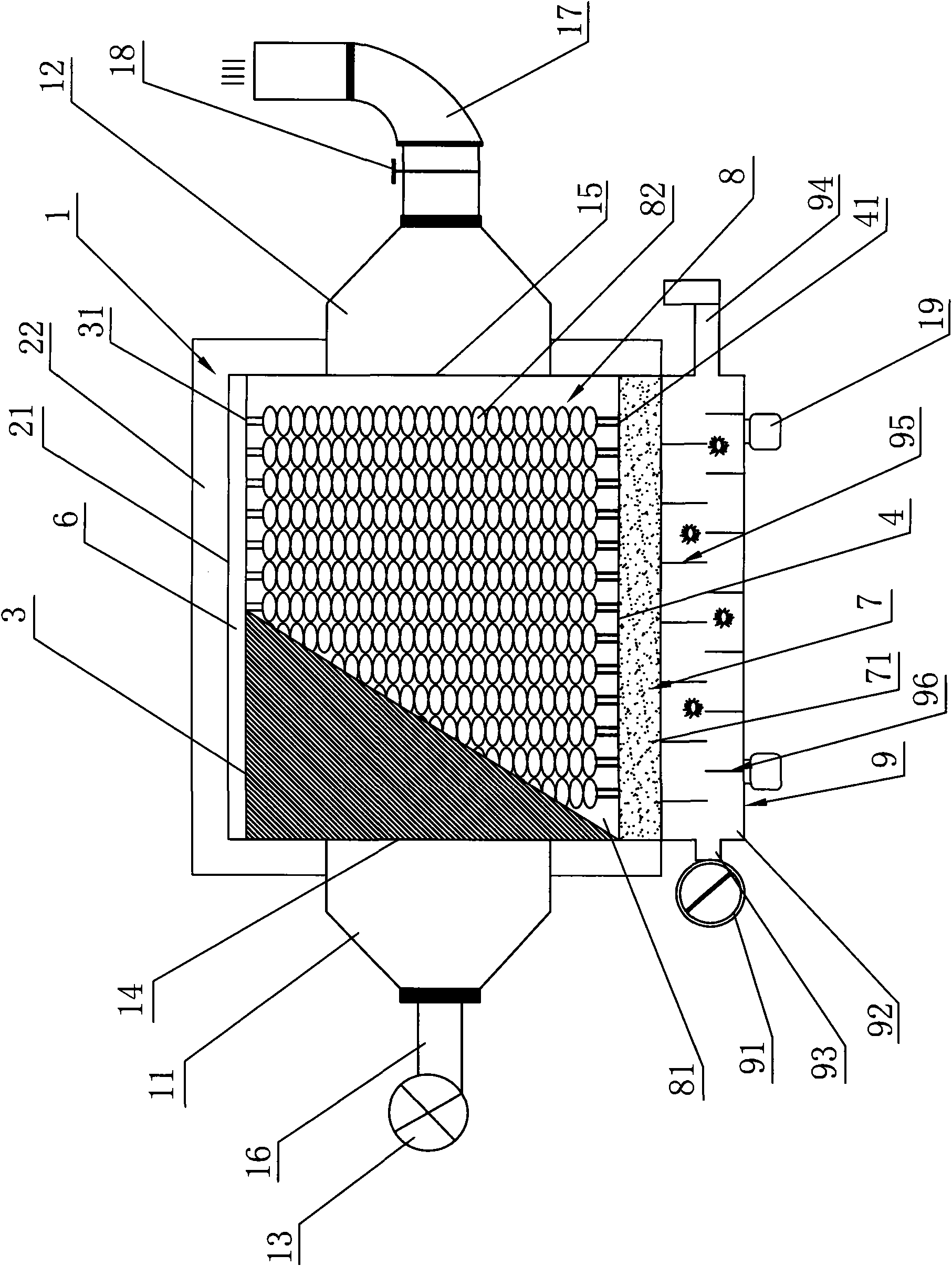
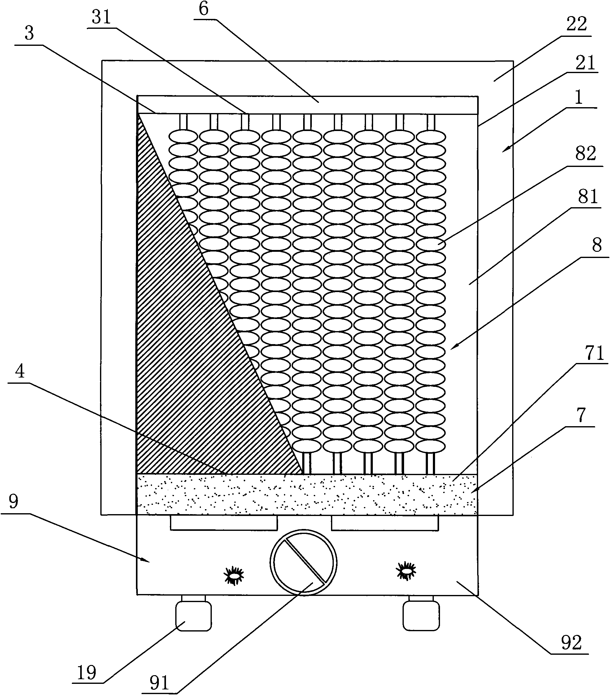
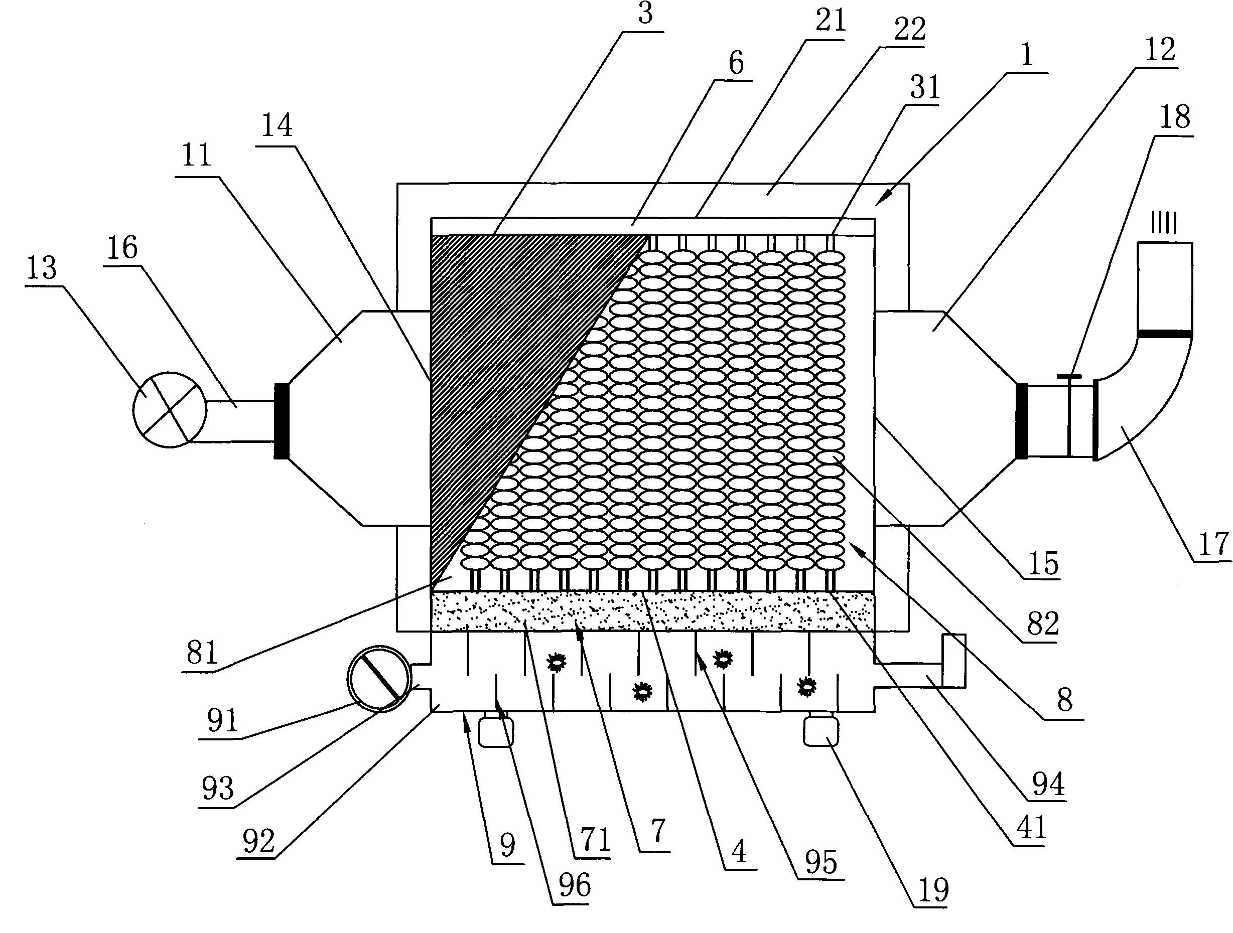
[0031] The spraying / painting production line special independent heat pipe (fin type) energy-saving heating / heat exchange system that the present invention proposes, such as figure 1 and figure 2 As shown, it comprises an insulated box body 1, and the insulated box body 1 is made of a steel plate box body 21 made of a steel plate and covered with a layer of insulation layer 22 outside the box body 21 made of the steel plate. A condensation chamber 6, a heat exchanger 8, and a liquid storage / heat transfer chamber 7 are arranged in sequence from top to bottom. The heat exchanger 8 is mainly composed of a heat exchange chamber 81 and several finned heat pipes 82 uniformly arranged in the heat exchange chamber 81. Composition, the finned heat pipe 82 communicates with the condensation chamber 6 and the liquid storage / heat transfer chamber 7 resp...


PUM


Abstract

The invention discloses an independent heat tube energy-saving heating / heat exchange system special for a spray coating / spray lacquer production line. The system comprises a heat preservation box body and is characterized in that: a condensing chamber, a heat exchanger and a liquid storage / heat transfer chamber are arranged in the heat preservation box body in turn from top to bottom; the heat exchanger mainly comprises a heat exchange chamber and a plurality finned heat tubes which are uniformly arranged in the heat exchange chamber; the finned heat tubes are communicated with the condensing chamber and the liquid storage / heat transfer chamber respectively; the liquid storage / heat transfer chamber is filled with a heat-conducting medium; the bottom of the heat preservation box body is connected with a combustion apparatus; two symmetrical sides of the heat preservation box body are connected with an air inlet fan housing and an air outlet fan housing respectively; the air inlet fan housing and the air outlet fan housing are communicated with the heat exchange chamber; and the air inlet fan housing is connected with a blower fan. The independent heat tube energy-saving heating / heat exchange system has the advantage that the (finned) heat tubes are used as heat radiating devices to improve coefficients of heat conductivity, increase the heat radiating area, reduce the heat conduction heat resistance and enhance the heat conductivity and the efficiency so as to improve the heat exchange efficiency of the system, reduce the fuel consumption and achieve the aim of saving energy.

Description

technical field [0001] The invention relates to a drying heating / heat exchange system, in particular to an energy-saving heating / heat exchange system with independent heat pipes for a spraying / painting production line. Background technique [0002] With the continuous and rapid development of my country's light industry, energy consumption in the production of household appliances, plastics, electronics, furniture, vehicles, cabinets and machinery industries has increasingly highlighted the energy cost problem caused by high energy consumption, while spraying / The high energy consumption of painting equipment is particularly prominent, especially the drying heating / heat exchange system in the production line of spraying / painting suspension track chain drying box. [0003] At present, the common types of drying heating / heat exchange systems mainly include fuel-fired heating tube type (light diesel oil), gas-fired heating tube type (natural gas), gas-fired heating tube type (pe...

Claims


Application Information

Patent Timeline
IPC IPC(8): F28D15/02B05D3/02
Inventor 沈双喜
Owner 宁波福威克能源科技有限公司
Why Eureka
Try Eureka