Re-condensation reclaiming system for evaporated gas of liquefied natural gas receiving station and reclaiming method thereof

A technology for liquefied natural gas and boil-off gas, which is applied to the boil-off gas re-condensation recovery system and its recovery field of LNG receiving station, can solve the problems of BOG not being completely absorbed or condensed, energy waste, difficult operation, etc. Stable condition, improved operation stability, good effect of fluctuation adaptability

Active Publication Date: 2010-11-10
佛山市天然气高压管网有限公司
View PDF5 Cites 43 Cited by
  • Summary
  • Abstract
  • Description
  • Claims
  • Application Information

AI Technical Summary

Problems solved by technology

At present, the design of the recondenser only considers the liquefaction function of BOG, and does not consider the buffer function of the suction end of the high-pressure pump. Since there is no buffer tank at the suction end of the high-pressure pump, the amount of BOG condensed in the re-condenser and the amount of LNG used to liquefy BOG are insufficient. When the high-pressure pump is supplied (or too much), the liquid level of the re-condenser will be out of control, and frequent liquid-level fluctuations will easily lead to the accident of pump trip when the high-pressure pump is turned on; at the same time, because the flow of LNG entering the re-condenser is based on quantitative The BOG flow rate and the recondenser outlet pressure set by the pressure signal source (PIC-1) at the suction end of the high-pressure pump are calculated by the ratio calculation module formula in the DCS (Distributed Control System), and the LNG flow rate is controlled according to the calculated value Control the opening of the valve (FV) to maintain the liquid level of the recondenser and keep the pressure at the suction end of the high-pressure pump constant, and the pressure signal source (PIC-1) at the suction end of the high-pressure pump needs to simultaneously adjust the LNG flow of another branch ( PV-1, PV-2) to ensure a constant pressure at the suction end of the LNG high-pressure delivery pump
Due to the complex control system

Method used


Image

  • Re-condensation reclaiming system for evaporated gas of liquefied natural gas receiving station and reclaiming method thereof
  • Re-condensation reclaiming system for evaporated gas of liquefied natural gas receiving station and reclaiming method thereof
  • Re-condensation reclaiming system for evaporated gas of liquefied natural gas receiving station and reclaiming method thereof

Examples


Embodiment 1

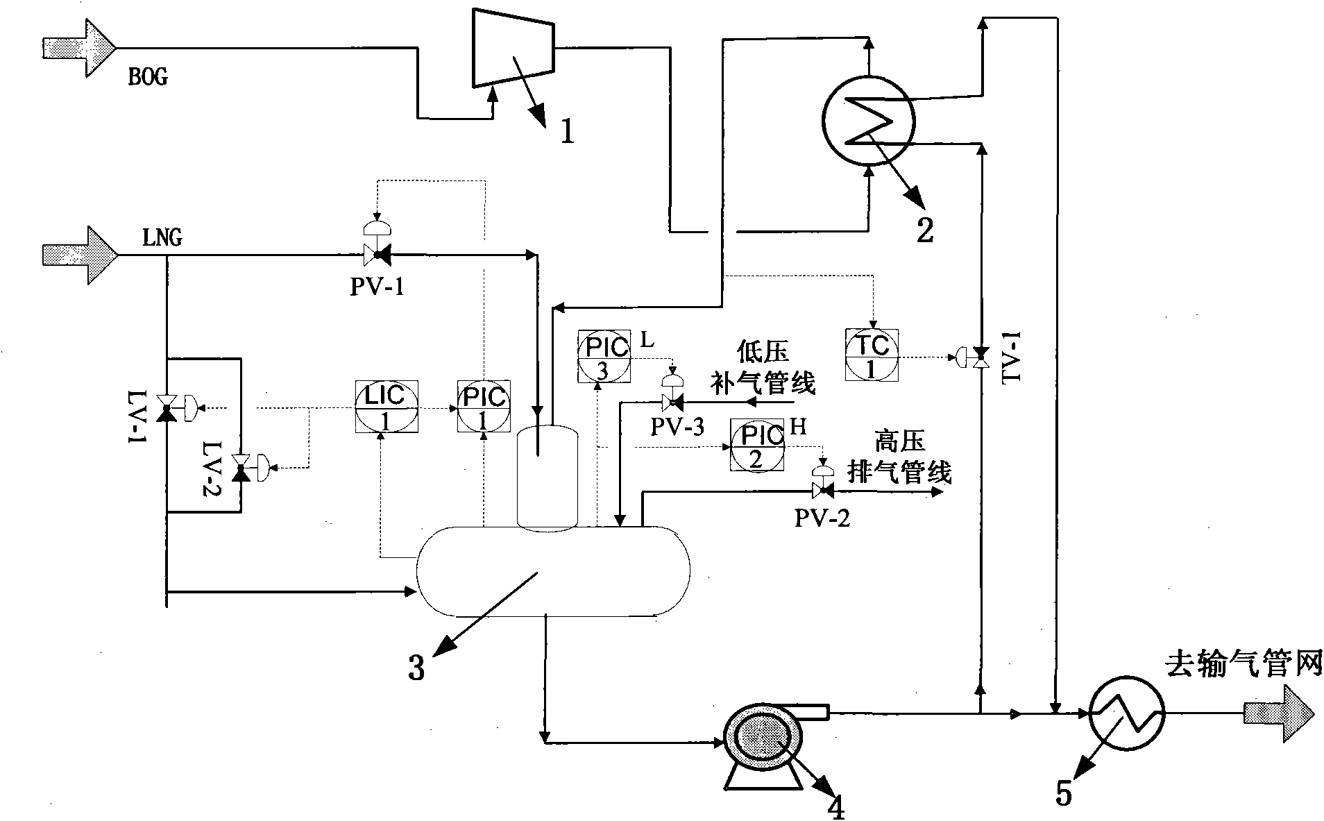
[0051] A recondensation recovery system for boil-off gas at a liquefied natural gas receiving station: the system includes a boil-off gas compressor ( Figure 3-1 ), evaporating gas precooling heat exchanger ( Figure 3-2 ), recondenser ( Figure 3-3 ), pressure controller (including PIC-1, PIC-2 and PIC-3) and liquid level controller LIC-1; the evaporated gas compressor, evaporated gas precooling heat exchanger and recondenser are connected in sequence, and the pressure The controller and the liquid level controller are respectively connected with the recondenser; the recondenser consists of a vertical condensation tower ( Pic 4-1 ) and high pressure pump buffer tank ( Figure 4-2 ), the vertical condensing tower is located above the buffer tank of the high-pressure pump.

[0052] The top of the vertical condensing tower is provided with a low-pressure liquefied natural gas I inlet ( Figure 4-4 ) and boil-off gas inlet ( Figure 4 -6), the vertical condensing tower is ...

Embodiment 2

[0055] A receiving station receives imported LNG by ship, and its molar composition is as follows: methane 88.774%, ethane 7.542%, propane 2.588%, isobutane 0.454%, n-butane 0.562%, isopentane 0.004%, nitrogen 0.074%. LNG storage tanks are two stocks of 1.6 x 10 5 m 3 The full-capacity concrete low-temperature atmospheric pressure storage tank, the operating pressure is 0.15Kg / cm 2 G, the LNG storage capacity of the two storage tanks is 147520t. The daily evaporation of LNG is less than 0.05% (mass fraction), under normal operating conditions, about 6.7t of BOG gas is produced per hour, the LNG output is 180t / h, and the pressure of the gas pipeline network is 95kg / cm 2g. Embodiment Using the BOG pre-cooling process designed by the present invention and the BOG recondensation recovery method with the high-pressure pump buffer tank, the cold capacity carried by LNG is used to pre-cool the compressed BOG gas, and the cold source comes from the low-temperature sent to the vapor...

Embodiment 3

[0067] A receiving station receives imported LNG by ship, and its molar composition is as follows: 96.6% methane, 1.97% ethane, 0.4% propane, 0.07% isobutane, 0.07% n-butane, and 0.89% nitrogen. There are 3 LNG storage tanks with a volume of 1.3×10 5 m 3 The underground storage tank, the operating pressure is 0.19Kg / cm 2 G, the total LNG reserves of the 3 storage tanks are 169950t. According to statistics, the daily evaporation of LNG is about 0.1% (mass fraction), under normal operating conditions, about 8.5t of BOG gas is produced per hour, the LNG output is 200t / h, and the pressure of the gas pipeline network is 78kg / cm 2 g. Embodiment Using the BOG pre-cooling process designed by the present invention and the BOG recondensation recovery method with the high-pressure pump buffer tank, the cold capacity carried by LNG is used to pre-cool the compressed BOG gas, and the cold source comes from the low-temperature sent to the vaporizer in the system High pressure LNG.

[0...


PUM


Abstract

The invention discloses a re-condensation reclaiming system and a re-condensation reclaiming method for evaporated gas of a liquefied natural gas receiving station. The system comprises an evaporated gas compressor, an evaporated gas pre-cooling heat exchanger and a re-condenser, wherein the re-condenser consists of a vertical condensing tower and a high-pressure pump buffer tank; and the vertical condensing tower is positioned above the high-pressure pump buffer tank. The bottom of the high-pressure pump buffer tank is provided with a brace, and a crossed vortex breaker is arranged in the brace. The reclaiming method comprises the following steps of: (1) compressing the evaporated gas, (2) pre-cooling the evaporated gas, (3) condensing and super-cooling the evaporated gas and (4) conveying secondary pressure of LNG. The design of the buffer tank improves the running stability of a high-pressure pump; the re-condenser operates and controls the system more stably and simply; and the system and the method reduce the energy consumption, and have good adaptability to gas conveying load fluctuation.

Description

technical field [0001] The invention belongs to the field of optimization and energy-efficient utilization of boil-off gas (BOG) recondensation system at a liquefied natural gas (LNG) receiving station, and particularly relates to a method of using the cold energy carried by the LNG itself at the LNG receiving station to prevent environmental leakage during the LNG storage and transportation process. The recondensation recovery system and its recovery method of BOG produced by LNG in LNG storage tanks, equipment, pipelines, etc. caused by heat and mechanical movement of equipment. Background technique [0002] Natural gas is an important resource to diversify energy supply, ensure energy security, improve the environment and increase energy efficiency. With the rapid growth of demand for natural gas, the gap between domestic demand and supply is also growing. According to the national energy development plan, my country will build about 10 LNG receiving stations in the Yang...

Claims


Application Information

Patent Timeline
IPC IPC(8): F25J1/00F28F27/00
Inventor 李亚军陈行水金光
Owner 佛山市天然气高压管网有限公司
Why Eureka
Try Eureka