
Control method of alternating voltage sensorless high voltage direct current transmission converter

A technology of high-voltage DC transmission and AC voltage, which is applied to the AC network to reduce harmonics/ripples, instruments, and reactive power compensation. It can solve problems such as slow transient response, affecting control effects, and difficult parameter adjustments. Improving dynamic response speed, avoiding zero-crossing offset, and simplifying the debugging process

Inactive Publication Date: 2010-11-10
SHANGHAI JIAO TONG UNIV
View PDF2 Cites 48 Cited by
  • Summary
  • Abstract
  • Description
  • Claims
  • Application Information

AI Technical Summary

Problems solved by technology

This method has good steady-state performance and tracking accuracy, but has the following disadvantages: (1) Since the grid voltage phase information is required for coordinate transformation, the accuracy of the voltage sensor and the interference from the field will cause measurement errors, so that the phase-locked loop cannot Accurate tracking of the grid phase leads to the fact that the d-axis voltage cannot be accurately oriented on the grid voltage vector after coordinate transformation, and there is still coupling between active and reactive power, which affects the control effect; (2) This method adopts a double closed-loop structure, which belongs to the current indirect control method. The state response speed is slow. Usually, in order to avoid the frequency resonance of the inner and outer rings, the frequency response speed of the outer ring is only about 1 / 5 of that of the inner ring, which makes the system recover slowly during the transient process and generates a large amount of reactive power, DC voltage and active power. The power overshoot is large, which may easily cause system overvoltage and overcurrent protection, resulting in the off-grid of the wind farm, affecting the connection of the wind farm to the grid, and having a large impact on the grid; (3) There are too many regulator parameters in the system itself, and the two ends The converter controls active power, reactive power, voltage, and current separately, requiring at least 8 PI regulators. There are too many adjustment parameters, and there is no effective setting method. Most of them rely on the simple calculation of the regulator engineering setting method, and then use experience Try it out, the actual project debugging is often very difficult; (4) The control method itself requires a lot of calculations, such as the sine and cosine functions of the phase angle of the power grid need to be calculated from multiple stationary coordinate systems to the rotating coordinate system, which affects the real-time performance of the system and affects the processing The device performance and circuit board process requirements are higher, and the cost increases
[0006] In summary, the transient response performance of the controller designed in this paper is not ideal, and the voltage sensor is used to obtain the system voltage phase information, which cannot work normally in the case of an asymmetric fault in the power grid, and the system will have a large overshoot; at the same time, the PI regulator is overshooting. Many, difficult to adjust parameters

Method used


Image

  • Control method of alternating voltage sensorless high voltage direct current transmission converter
  • Control method of alternating voltage sensorless high voltage direct current transmission converter
  • Control method of alternating voltage sensorless high voltage direct current transmission converter

Examples


Embodiment Construction

[0026] Embodiments of the present invention are described in detail below in conjunction with the accompanying drawings: the following embodiments are implemented on the premise of the technical solutions of the present invention, and detailed implementation methods and processes are provided, but the protection scope of the present invention is not limited to the following implementations example.

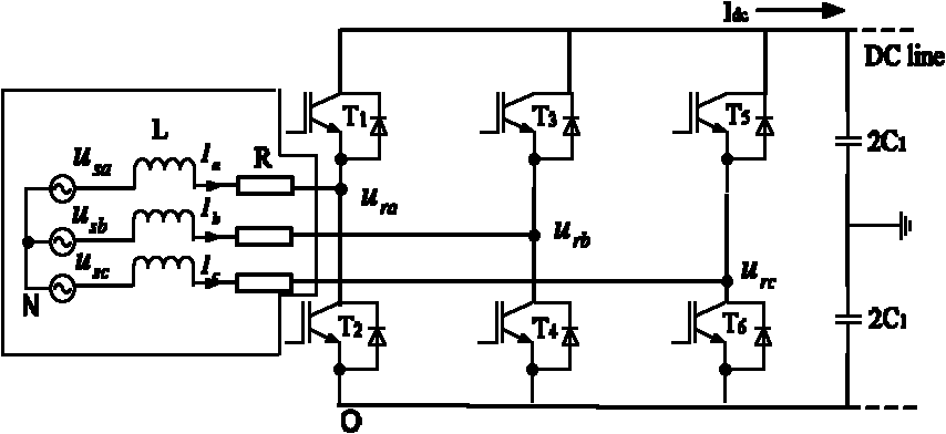
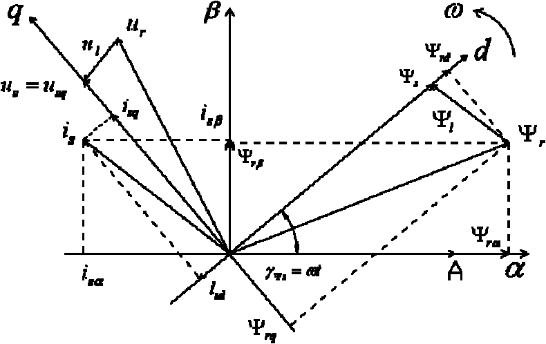
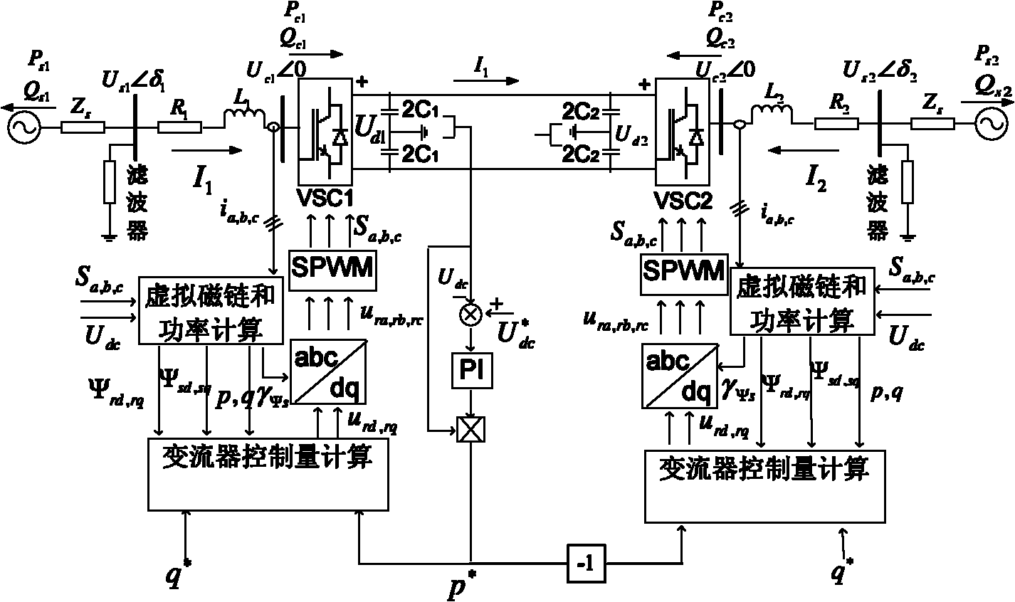
[0027] likefigure 1 As shown, the dotted line in the figure is the equivalent motor, and the concept of virtual flux linkage is derived from the hypothetical virtual motor. It is considered that the line voltage u ab , u bc , u ca It is induced by the virtual flux linkage. For a two-level converter, according to the voltage equation of the AC side of the converter ( are the grid line voltage vector, the AC side voltage vector of the converter and the voltage vector on the inductance L), by detecting the DC voltage and the switching function S i (i=a, b, c) can get the virtua...


PUM


Abstract

The invention discloses a control method of an alternating voltage sensorless high voltage direct current transmission converter, belonging to the technical field of electrical equipment and comprising the following steps: establishing a stator resistor and an inductor for a virtual motor; building relative position relationships among a current vector, a voltage vector and a flux linkage vector, and analyzing a vectorgram; establishing a converter and flux linkage mathematic model, and calculating a virtual flux linkage vector of a system to obtain a power feedback quantity of the system; acquiring an active control signal and a reactive control signal of the system through a direct power control algorithm, and generating a PWM trigger converter for respectively and independently controlling the active power and reactive power of the system; and utilizing MATLAB simulation software to set up a system model for verifying, and obtaining a systematic selection device when the verification is successful. By utilizing Matlab / Simulink to set up a corresponding simulation model, the designed method is verified to have rapid response speed, the voltage and power after startup can still reach stable values after about 2 power frequency periods and have high steady state precision.

Description

technical field [0001] The invention relates to a control method in the field of electrical technology, in particular to a control method for a high voltage direct current transmission (VSC-HVDC) converter without an AC voltage sensor. Background technique [0002] The utilization and research of various renewable energy sources such as wind energy have been paid more and more attention by major developed countries in the world, and the utilization of wind energy has become one of the effective means to solve the current energy crisis and environmental sustainable development. Offshore wind energy resources are abundant and will be an important way of wind power generation in the future. Offshore wind power long-distance DC transmission has become one of the key technologies in the development of new energy. In recent years, fully controlled devices such as IGBTs have been used more and more in new VSC-HVDC. Although the traditional DC transmission technology is relatively...

Claims


Application Information

Patent Timeline
IPC IPC(8): H02J3/38H02J3/18H02J3/01G06F17/50
CPCY02T10/82Y02E40/30Y02E40/40
Inventor 王国强王志新李爽
Owner SHANGHAI JIAO TONG UNIV
Learn More