Equipment for preparing ceramic powder by humidifying dry powder

A ceramic powder and equipment technology, applied in the field of production and processing equipment, can solve the problems of high energy consumption cost, unstable particle size gradation, failure to meet the requirements of ceramic production, etc.

Active Publication Date: 2010-11-17
FOSHAN RONGZHOU NO 2 BUILDING CERAMICS FACTORY
View PDF4 Cites 13 Cited by
  • Summary
  • Abstract
  • Description
  • Claims
  • Application Information

AI Technical Summary

Problems solved by technology

This kind of production process consumes a lot of energy, and the flue gas produced during the drying process has high sulfur content and large dust, which requires additional desulfurization and dust removal treatment, and is not easy to eliminate. Requirements for low-carbon and environmentally friendly production encouraged by the state
For this reason, a process of semi-dry granulation and powder production has also appeared in the ceramic industry, but its powder processing equipment only uses stirring paddles or stirring rods for granulation, so spherical-like particles in the powder particles account for The ratio is not high, the particle size gradation is unstable, and the fluidity of the powder is not ideal, so it is difficult to meet the requirements of the automatic brick press for the powder.
On the other hand, although there are semi-dry granulation technology and granulation equipment in the food and pharmaceutical industries, due to the large differences in the hardness, specific gravity, particle size, viscosity and other physical properties of various raw materials used in ceramic formulations, ceramic powder particles The chemical composition difference between them is large, and the particle size distribution is unstable. These granulation equipment in the food and pharmaceutical industries cannot be suitable for the granulation of ceramic powder, and cannot meet the requirements of ceramic production.
In addition, due to the special material properties of ceramic powder, especially the high viscosity, during the operation of traditional equipment, ceramic powder is very easy to stick to the bottom and inner wall of the equipment, or accumulate agglomerates at the bottom of the stirring paddle, which affects the stirring work ;Because the ceramic powder sticks to the bottom and inner wall of the equipment, the volume of granulation is reduced, and the output of qualified powder is also reduced, which affects the production efficiency. The production process and product quality are extremely unstable, and the technology is not yet available. mass production applications

Method used


Image

  • Equipment for preparing ceramic powder by humidifying dry powder
  • Equipment for preparing ceramic powder by humidifying dry powder
  • Equipment for preparing ceramic powder by humidifying dry powder

Examples


Embodiment 1

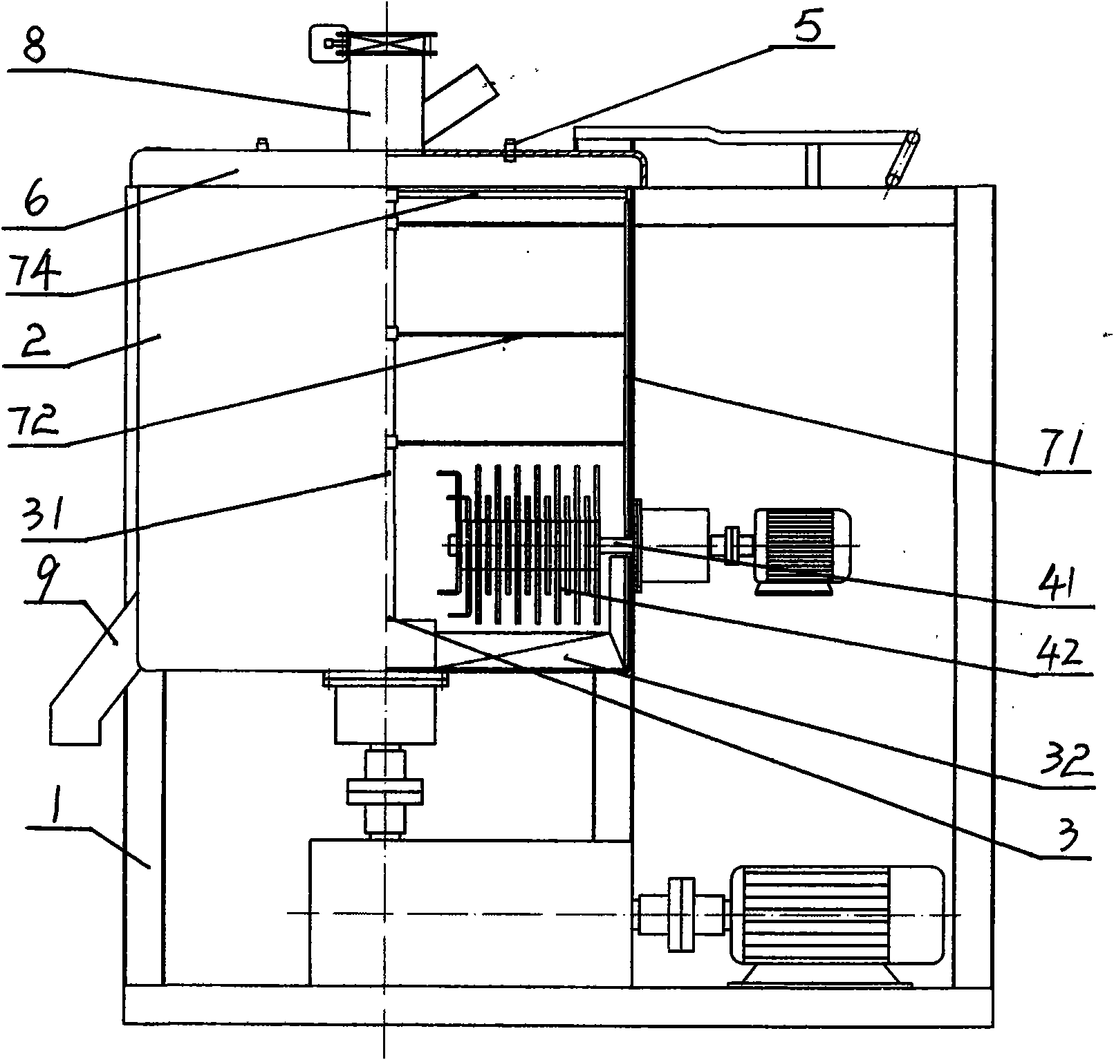
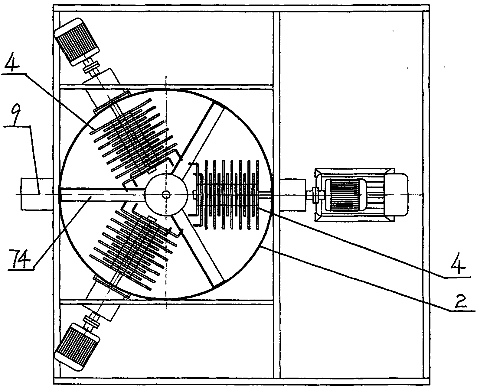
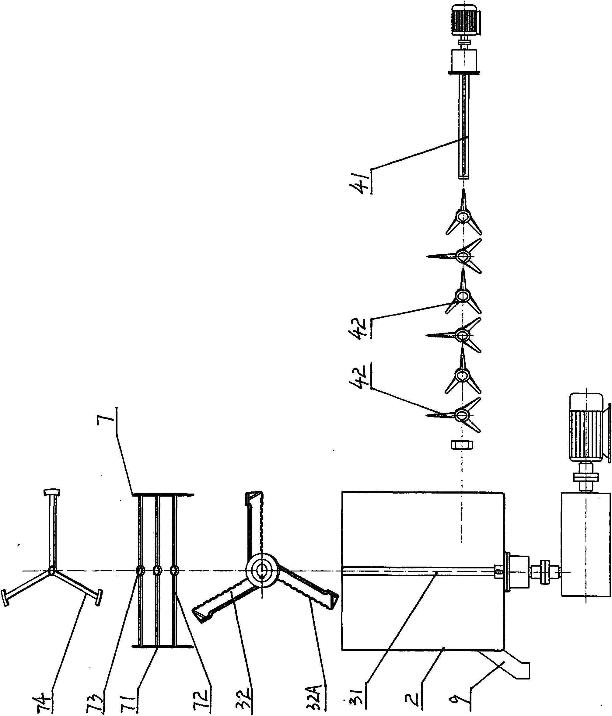
[0017] Embodiment one, see Figure 1-5 , This embodiment is mainly composed of a frame 1, a granulation tank 2, a stirring mechanism 3, a cutting mechanism 4, a scraping mechanism 7, an inlet 8, an outlet 9, and a power mechanism. The cylindrical granulation tank 2 is arranged on the frame 1; the sealing cover 6 at the top of the granulation tank 2 is provided with an atomizing water supply nozzle 5 and a feed port 8; the stirring mechanism 3 is arranged at the bottom of the granulation tank 2, and The stirring shaft 31 and the stirring paddle 32 are composed of the stirring paddle 32, which is a multi-blade structure. The plane of the paddle and the stirring shaft 31 form a 75-degree inclination angle. There are three paddles. Turning, mixing, granulating. One side edge 32A of its rotating direction of the paddle of stirring paddle 32 is tooth shape, and the tooth shape between each paddle is misplaced and arranged (as Figure 8 shown). The cutting mechanism 4 is arranged ...

Embodiment 2

[0020] Embodiment 2. The structure of this embodiment is basically similar to that of Embodiment 1. It also consists of a frame 1, a granulation tank 2, a stirring mechanism 3, a cutting mechanism 4, a scraping mechanism 7, an atomizing water supply nozzle, a sealing cover, and a row Composed of air port, material inlet, material outlet and power mechanism. The main difference is that the paddle plane of the stirring paddle forms an inclination angle of 65 degrees with the stirring main shaft, and there are five paddle blades. Four sets of cutting mechanisms 4 are arranged symmetrically in the granulation tank 2, and each set of cutting mechanisms has four cutting blades 43 fastened to them. On the cutting main shaft; the cutting blade 43 is a three-bladed knife, and its blade all has a cutting edge 43A, and the blade end is upwardly bent at 90 degrees (as Figure 6 , Figure 7 ), the cutting blades 43 are equally staggered and superimposed on the cutting main shaft; . In o...

Embodiment 3

[0021]Embodiment 3, the structure of this embodiment is basically similar to that of Embodiment 1, and it is also composed of a frame 1, a granulation tank 2, a stirring mechanism 3, a cutting mechanism 4, a scraping mechanism 7, an atomizing water supply nozzle, a sealing cover, and a row Composed of air port, material inlet, material outlet and power mechanism. The main difference is that the paddle plane of the stirring paddle is at an angle of 55 degrees to the stirring spindle, and there are six paddles, and six sets of cutting mechanisms are set in the granulation tank, and each set of cutting mechanisms has eight cutting blades fastened to the cutting spindle The upper composition; the cutting blade is a single-blade knife with a hook at the end of the blade, and the cutting blades are staggered and superimposed on the main shaft; The length is one-third of the radius of the granulation tank; the cutting blade is driven to rotate by the cutting spindle to realize the cu...


PUM


Abstract

The invention relates to equipment for preparing ceramic powder by humidifying dry powder. The equipment consists of a machine frame, a pelleting tank, a stirring mechanism, an atomization water-supplying sprayer, a sealed cover, a feed inlet, a discharge outlet and a power mechanism, wherein the stirring mechanism is axially arranged at the bottom in the pelleting tank; a main stirring shaft drives a stirring paddle to rotate; a scraping mechanism is additionally arranged in the pelleting tank and above the stirring paddle; a scraper blade of the scraping mechanism rotates by abutting against the inner wall of the pelleting tank; a cutting mechanism is arranged in the pelleting tank and between the stirring paddle and the scraping mechanism; and a cutting knife of the cutting mechanism is driven by a main cutting shaft to rotate. Due to the structure, the equipment has the advantages of clear processing functions of stirring, scraping, cutting, pelleting and the like, high controllability, high proportion of sphere-like grains in the produced powder, high flowability, capacity of efficiently producing the powder meeting the forming requirement of an automatic brick press, compact structure, high production efficiency and low energy consumption. The equipment can be widely applied to raw material processing in ceramic industries.

Description

technical field [0001] The invention belongs to production and processing equipment in the ceramic industry, in particular to equipment for processing and granulating ceramic raw materials to prepare powder. Background technique [0002] The traditional ceramic raw material processing and granulation method belongs to the wet process, which is to use a ball mill to add about 35% water to grind the bulk ceramic raw material into a fine ceramic slurry, and then dry the slurry through a spray drying tower. , dried from about 35% moisture to about 7% moisture, and made into powder suitable for automatic brick press molding. This kind of production process consumes a lot of energy, and the flue gas produced during the drying process has high sulfur content and large dust, which requires additional desulfurization and dust removal treatment, and is not easy to eliminate. Requirements for low-carbon and environmentally friendly production encouraged by the state. For this reason,...

Claims


Application Information

Patent Timeline
Patent Type & Authority Applications(China)
IPC IPC(8): C04B35/626
Inventor 罗明坚
Owner FOSHAN RONGZHOU NO 2 BUILDING CERAMICS FACTORY
Why Eureka
Try Eureka