Eureka AIR delivers breakthrough ideas for toughest innovation challenges, trusted by R&D personnel around the world.

Micro-nano-alloy bimetal composite material preparation technique and device thereof

A composite material and preparation process technology, which is applied in the field of metal composite materials to achieve the effects of increased reaction driving force, increased contact area and low preparation cost

Active Publication Date: 2010-12-01
泰州海天机械配件有限公司
View PDF14 Cites 23 Cited by
  • Summary
  • Abstract
  • Description
  • Claims
  • Application Information

AI Technical Summary

Problems solved by technology

[0016] The purpose of the present invention is to make full use of the low melting point properties of nano-metals, by adding certain properties in nano-metal alloys, it can suppress cladding coating cracks, reduce the sensitivity of cladding coating cracks, and improve the wear resistance and corrosion resistance of coatings. Additives for corrosion resistance, oxidation resistance and thermal shock resistance can solve the shortcomings of existing cladding materials and nanomaterials, and provide a new type of bimetallic composite material preparation process and equipment to make the material into nano or micro-nano bimetal Composite materials, realize the effective compounding of nano-metal alloys and metal materials, and give full play to the excellent characteristics of nano-materials, so as to prepare new high-performance nano-metals with better performance that can meet the preparation of thin-layer cladding layers and large-thickness cladding layers at the same time Alloy surface composite material, obtain a large thickness nano-alloy bimetallic composite material preparation process and equipment with simple preparation process, low cost, and good product performance

Method used


Image

  • Micro-nano-alloy bimetal composite material preparation technique and device thereof
  • Micro-nano-alloy bimetal composite material preparation technique and device thereof
  • Micro-nano-alloy bimetal composite material preparation technique and device thereof

Examples


Embodiment 1

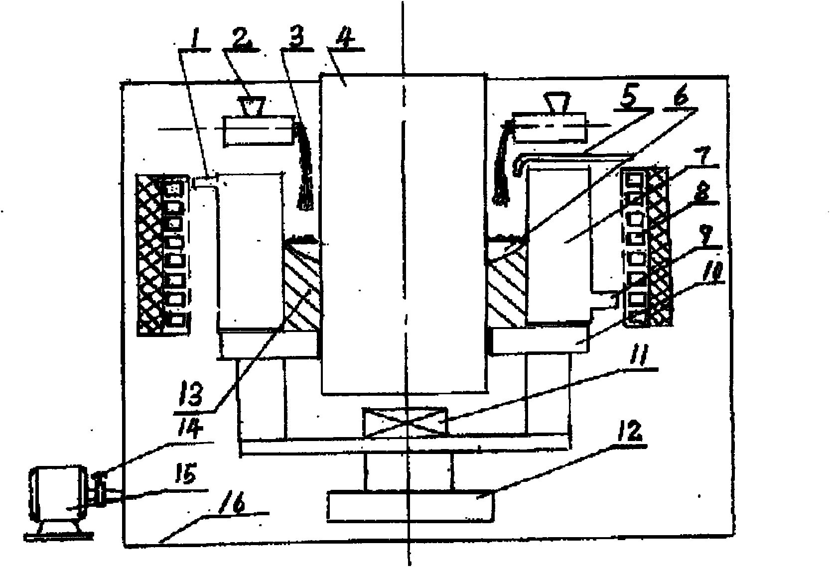
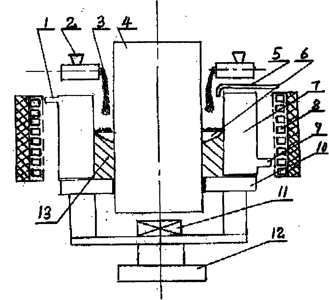
[0032] Example 1: figure 1 It is a vacuum induction cladding equipment. The equipment consists of water outlet pipe 1, particle feeder 2, alloy powder 3, workpiece 4, inert gas delivery pipe 5, molten pool 6, forming mold 7, frequency conversion induction heater 8, water inlet pipe 9, base 10, high-energy ultrasonic Vibrator 11, lifting and ingot drawing equipment 12, cladding layer 13, vacuum pump valve 14, vacuum motor 15, and vacuum sealing cover 16; 1 to 6 particle feeders 2 are installed on the upper part of the forming mold 7, and the A variable frequency induction heater 8 is installed on the outside of the molding die 7, a base 10 and a lifting ingot device 12 are installed on the bottom of the molding die 7, a high-energy ultrasonic vibrator 11 is installed on the bottom or upper part or side of the molding die 7, and an inert gas The conveying pipe 5 is installed on the top of the forming mold 7, and the vacuum sealing cover 11 seals the forming mold 7 equipment. Th...

Embodiment 2

[0034] Example 2: In figure 2 in, with figure 1 The difference is that the induction cladding equipment is not installed in a vacuum sealed enclosure.

[0035] When work starts, first put Cr 12 MoV cold work die steel is prepared into powder, or metal and alloy powder according to Cr 12 The alloy composition of MoV cold work die steel material is prepared, and then 0.4% Y is added in it according to the mass percentage 3 o 2 , 0.6% MgO, 0.5% CaF 2 , 0.25% Nb, 0.30% TiB, 0.15% TiN, 0.25% VN, and the rest is Fe. After proportioning its component raw materials, put them into a high-energy stirring ball mill for stirring ball milling to prepare micro-nano or nano-alloy powders; then Add 8% rosin oil binder to the above alloy powder, make it into granules or powder after mixing, dry it in the air or dry it at a temperature of 80 degrees, add it to the granule feeder, and clean the surface The processed workpiece 4 is placed in the forming mold 7, the forming mold 7 is fixed ...

Embodiment 3

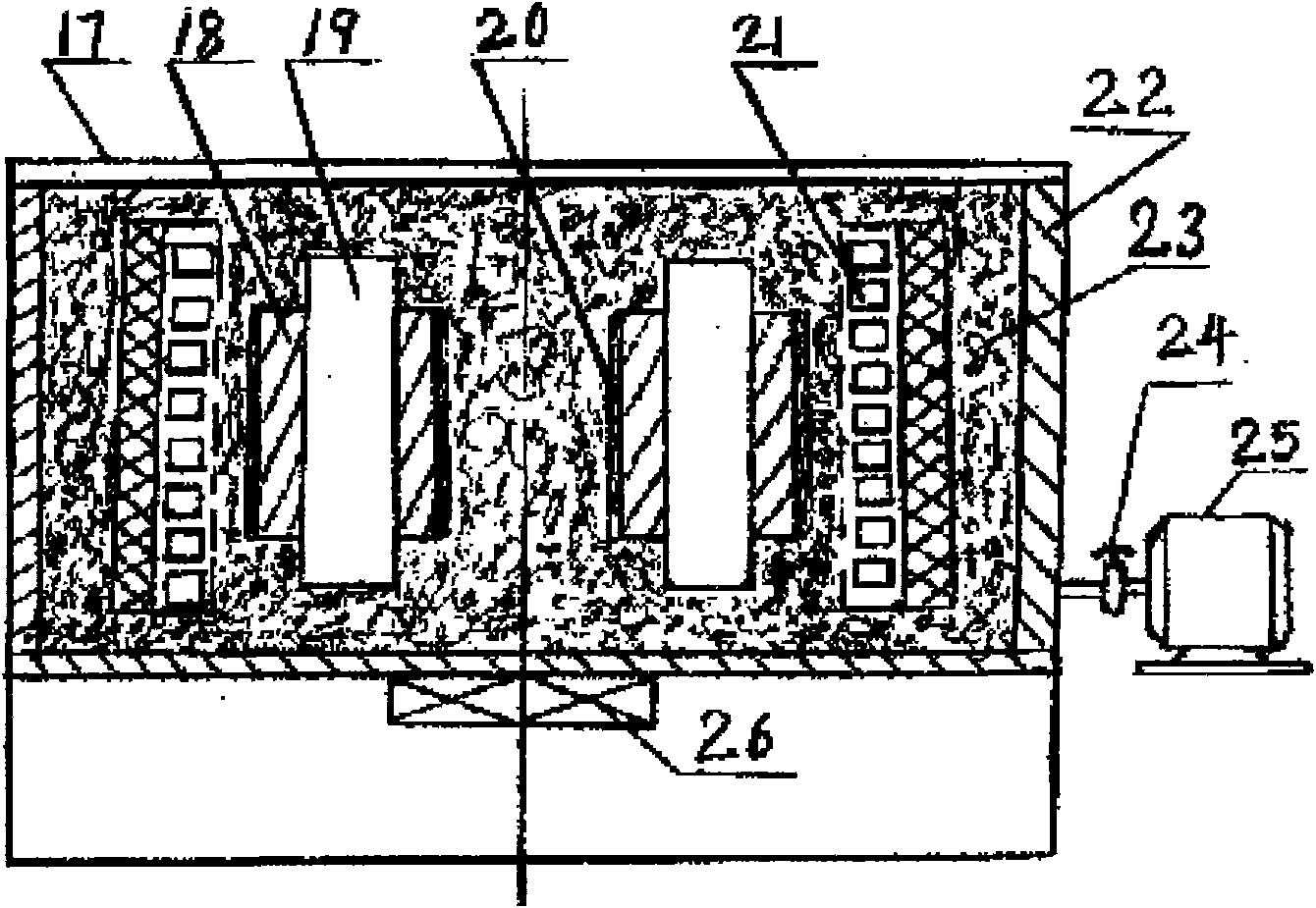
[0037] Example 3: image 3 It is a vacuum induction melting equipment. The equipment consists of box cover 17, cladding layer 18, workpiece 19, protective coating 20, frequency conversion induction heater 21, box body 22, manufacturing sand 23, vacuum pump valve 24, vacuum pump motor 25, vibrator 26, frequency conversion induction heater 21 is installed inside the box body 22, and the vibrator 26 is installed on the bottom or side of the box body 22. The vibrator 22 is mechanical vibration or ultrasonic vibration. The frequency of the frequency conversion induction heater 21 can be divided into steps from 200Hz to 500kHz. To adjust, the vacuum pump is installed on either side of the casing 22, and is connected with the vacuum pump valve 24 and the vacuum pump through a pipeline.

[0038] At the beginning of the work, the high chromium cast iron is first prepared into powder, or metal and alloy powder are used according to Cr 12 The alloy composition of MoV cold work die stee...


PUM


Abstract

The invention relates to a micro-nano-alloy bimetal composite material preparation technique and a device thereof; one of wear-resistant and corrosion-resistant ferrous metal material, non-ferrous metal material and various self-fluxing alloy is prepared into power; then, the powder is added with less than or equal to 0.8% of one or combination in CeO2, Y2O3 and La2O3, 0.3-1.5% of MgO, 0.3-1.8% of CaF2, 0.0-1.5% of B, 0.1-0.8% of Nb, 0.1-1.0% of Ti, 0.1-2.0% of grain refining and recrystallization inhibitor according to the mass percent; or the powder is added with 1-40% of carbide, nitride, micro-nano or nano particles of boride; and the mixture is put into a high-energy stirring ball grinding mill for grinding and ball milling, so that the micro-nano or nano alloy powder can be prepared. A variable frequency induction heating device is adopted for cladding and melting vacuum or inert gas, so that a workpiece can be melted and coated with a micro-nano or nano scale alloy cladding layer which has the grain size of 0.1-35mm and is wear-resistant and corrosion-resistant, and the bimetal composite material can be prepared. The invention overcomes the defects in various coating techniques in China at present, can complete the preparation of the workpiece with the cladding layer having high thickness for once, does not need repeated coating and sintering, has high material utilization rate, low machining allowance and preparation cost, simple preparation technique and high production efficiency.

Description

technical field [0001] The invention belongs to the technical field of metal composite materials, and relates to a micro-nano alloy bimetal composite material and a preparation method thereof, in particular to a preparation process and equipment for a micro-nano alloy bimetal composite material. Background technique [0002] Bimetallic composite materials are composites of two or more metal materials with different properties through a certain process, so that different parts of the material or parts have different properties to meet the requirements of use. It is different from dispersion-strengthened materials. Layered composite materials are not one material dispersed in another material, but each component material forms one or several wholes, and the components are composited by interface bonding. One, the composite methods mainly include liquid-solid composite, liquid-liquid composite, solid-solid composite and so on. It is usually an alloy with high mechanical proper...

Claims


Application Information

Patent Timeline
IPC IPC(8): B22D19/16B22D23/06C22C1/04B22D27/08B22D27/20
Inventor 丁家伟丁刚耿德英孙健强颖怀郭长庆
Owner 泰州海天机械配件有限公司
Why Eureka
Eureka Blog
Learn More