Exterior wall external insulation composite wall body with support
A technology for external thermal insulation of external walls and composite walls is applied in the field of external thermal insulation composite walls of buildings, which can solve the problems of poor natural fire prevention, failure to solve thermal bridges at openings, stress concentration, etc., so as to reduce heat transfer heat loss Effect
- Summary
- Abstract
- Description
- Claims
- Application Information
AI Technical Summary
Problems solved by technology
Method used
Image
Examples
specific Embodiment approach 1
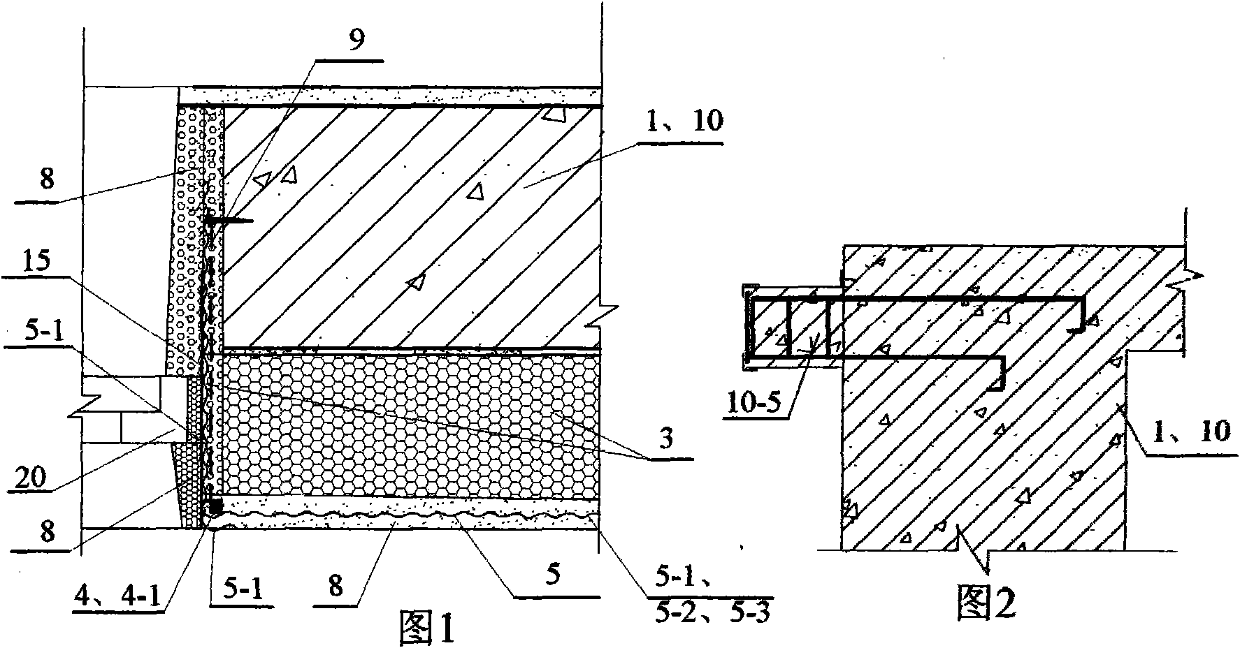
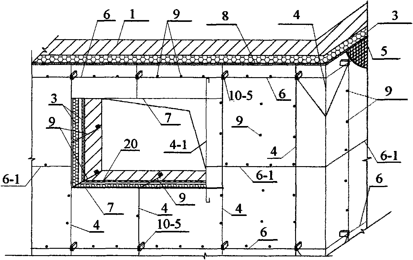
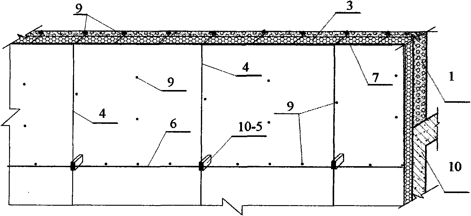
[0074] Specific implementation mode one: see Figure 1 to Figure 6 , a supported external thermal insulation composite wall of the present embodiment consists of a base wall 1, a concrete cantilever beam support 10-5, an insulation layer 3, a mesh tensile material 5, a vertical steel bar 4, and a protection layer 8, doors and windows 20, and the main building structure 10; the base wall 1 is a concrete wall, a load-bearing masonry wall, a non-load-bearing lightweight masonry filling wall, or a wall made of steel and wood or bamboo; the insulation layer 3 It is polymer thermal insulation material or mineral wool felt or plant straw board or paper honeycomb board or thermal insulation mortar or foamed concrete; the mesh tensile material 5 is alkali-resistant mesh cloth 5-1 or metal mesh 5-2 or bamboo reinforcement Net 5-3; the protective layer 8 is cement mortar or fine stone concrete, or modified cement mortar or fine stone concrete, or thermal insulation mortar or EPS board th...
specific Embodiment approach 2
[0083] Specific implementation mode two; see image 3 , Figure 4 , Image 6 The difference between this embodiment and Embodiment 1 is that this embodiment increases the upper and lower horizontal steel bars 7 of the hole, and the upper and lower horizontal steel bars 7 of the hole are connected with the vertical steel bars 4 on both sides of the hole. The upper and lower horizontal steel bars 7 of the hole are usually Φ4 galvanized steel bars and the vertical steel bars 4 on both sides are wound and bound.
specific Embodiment approach 3
[0084] Specific implementation mode three: see image 3 , the difference between this embodiment and embodiment one or two is that this embodiment adds additional vertical reinforcement 4-1; the additional vertical reinforcement 4-1 is located on both sides or one side of the hole, and the additional vertical reinforcement 4-1 is up and down The end is anchored in the protective layer 8, the upper and lower horizontal reinforcement bars 7 of the hole are connected with the additional vertical reinforcement bars 4-1 on both sides, or the upper and lower horizontal reinforcement bars 7 of the hole are connected with the additional vertical reinforcement bars 4-1 on one side and the vertical reinforcement bars 4 on the other side, The mesh tensile material 5 is fixedly connected with the additional vertical reinforcement 4-1.
[0085] Usually a concrete cantilever beam support is set at the edge of the opening, and the vertical reinforcement 4 is located at the edge of the openin...
PUM
 Abstract
Description
Claims
Application Information
 - R&D
- Intellectual Property
- Life Sciences
- Materials
- Tech Scout
- Unparalleled Data Quality
- Higher Quality Content
- 60% Fewer Hallucinations
Browse by: Latest US Patents, China's latest patents, Technical Efficacy Thesaurus, Application Domain, Technology Topic, Popular Technical Reports.
© 2025 PatSnap. All rights reserved.Legal|Privacy policy|Modern Slavery Act Transparency Statement|Sitemap|About US| Contact US: help@patsnap.com


