

Electrochemical device for wastewater treatment and method for treating wastewater by using same
A wastewater treatment and electrochemical technology, applied in chemical instruments and methods, water/sewage treatment, water/sludge/sewage treatment, etc., can solve the problems of expensive ion-exchange membranes, low efficiency, unsuitable for advanced sewage treatment, etc. Achieve the effect of reducing energy consumption, improving degradation efficiency and reducing processing time
- Summary
- Abstract
- Description
- Claims
- Application Information
AI Technical Summary
Problems solved by technology
Method used
Image

Examples
Embodiment 1
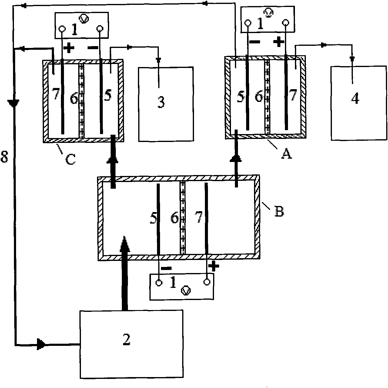
[0078] as attached figure 1 As shown, the electrochemical device of the present invention is composed of power supply, primary electrolytic cell B, electrolytic cell A, electrolytic cell C, cathode, permeable isolation material part, anode, raw water pool, purified water collector and concentrated solution collection pool. Each of the electrolyzers includes a rectangular tank body made of phenolic resin, reticulated (rhombic size, 12.5 × 4.5mm) Ti-IrO 2 (The substrate is Ti, the coating is 20-50μm thick IrO 2 ) anode, copper-based alloy plate (copper 64.5%-66.5%, nickel 16.5%-18.5%, the balance is zinc) cathode and permeable isolation material with a thickness of 0.1mm nylon cloth. , its electrode area is 238cm 2 (14cm×17cm), the electrode spacing is 8mm. Using a DC power supply produced by Shanghai Wenbo Electric Co., Ltd., apply a DC current between the anode and the cathode with a current density of 5mA / cm 2 .
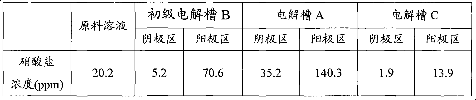
[0079] The raw material solution is a self-prepared sodiu...
Embodiment 2
[0084] In this example, nitrate in water was removed in the same manner as in Example 1, but the current density was changed. In this embodiment, the current density of primary electrolyzer B is 40mA / cm 2 , the current density of electrolytic cell A is 80mA / cm 2 , the current density of electrolytic cell C is 20mA / cm 2 After 10 minutes, the nitrate concentration of the water body in the Yin and Yang areas of each electrolytic cell was measured, and the test results are shown in Table 2.
[0085] Table 2: Nitrate concentration in the water body in the cathode and anode areas of each electrolyzer
[0086]
[0087] It can be seen that with the increase of the current density, the concentration of nitrate nitrogen can be reduced to below 1ppm, and the concentration of the anode area can be concentrated to 160ppm, but the high current density will lead to increased energy consumption.
Embodiment 3
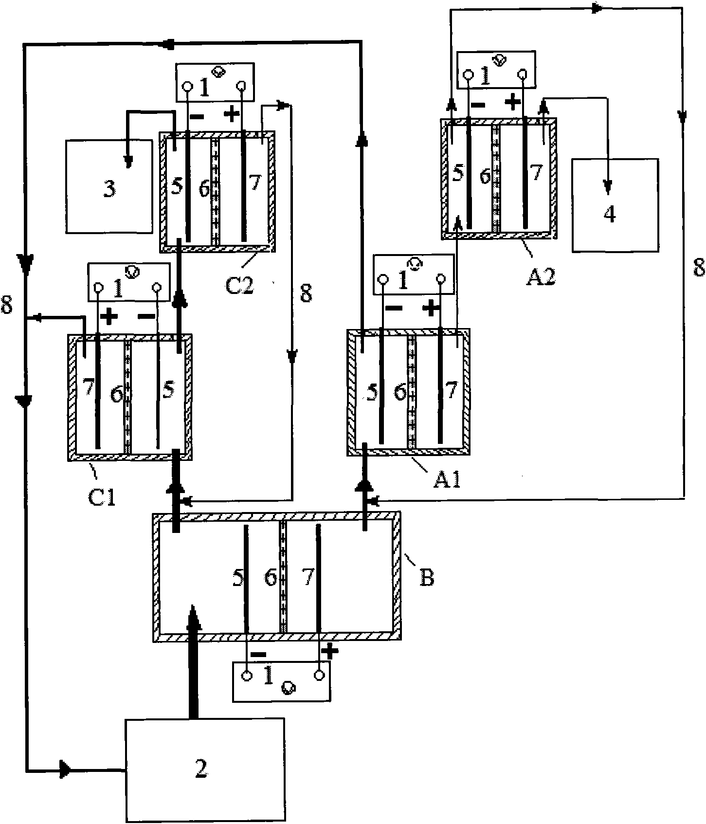
[0089] as attached figure 2 As shown, five electrolyzers are used in combination, that is, a primary electrolyzer B, electrolyzers A1 and A2, and electrolyzers C1 and C2.
[0090] The water flowing out from the anode area of the primary electrolytic cell B enters from the bottom of the cathode area of the electrolytic cell A1, and then flows out from the top of the anode area and the cathode area respectively; the water flowing out from the top of the cathode area of the electrolytic cell A1 returns to the raw water pool 2 for circulation Electrolysis; the water body flowing out from the top of the anode area of electrolytic cell A1 enters the bottom of the cathode area of electrolytic cell A2, and then flows out from the top of its anode area and cathode area; the water body flowing out from the top of the cathode area of electrolytic cell A2 enters the bottom of the cathode area of electrolytic cell A1; The water flowing out from the top of the anode area of ...
PUM
| Property | Measurement | Unit |
|---|---|---|
| Electrode area | aaaaa | aaaaa |
Abstract
Description
Claims
Application Information