Optical laminate, polarizing plate, and display apparatus using the same
A technology of optical laminates and optical functional layers, applied in the direction of optics, optical elements, polarizing elements, etc., can solve the problems of poor light resistance and inability to maintain antistatic performance, and achieve excellent scratch resistance, scratch resistance and elongation The effect of improving the rate and softness and excellent saponification resistance
- Summary
- Abstract
- Description
- Claims
- Application Information
AI Technical Summary
Problems solved by technology
Method used
Image
Examples
manufacture example 1
[0225] (Manufacture example 1) Manufacture of synthetic smectite
[0226] Add 4L of water to a 10L beaker to dissolve No. 3 water glass (SiO 2 28%, Na 2 O 9%, molar ratio 3.22) 860g, while stirring, add 95% sulfuric acid 162g in one go, obtain silicate solution. Next, dissolve MgCl in 1 L of water 2 ·6H 2 O superior grade pure reagent (purity 98%) 560g, it is added in the aforementioned silicic acid solution and is prepared into homogeneous mixed solution. This was added dropwise to 3.6 L of 2N-NaOH solution over 5 minutes while stirring. The resulting reaction precipitate was immediately filtered with a cross-flow filtration system [cross-flow filter (ceramic membrane filter: pore size 2 μm, tube type, filtration area 400 cm] manufactured by Nippon Barriers Co., Ltd. 2 ), pressurization: 2kg / cm 2 , filter cloth: Tito wheel 1310] After filtering and fully washing, add 200ml of water and 14.5g of Li(OH)·H 2 The solution composed of O was made into a slurry. Move it int...
manufacture example 2
[0227] (Production Example 2) Production of Synthetic Smectite-Based Layered Organoclay A
[0228] 20 g of the synthetic smectite synthesized in Production Example 1 was dispersed in 1000 ml of tap water to prepare a suspension. Be dissolved with the aqueous solution 500ml of the quaternary ammonium salt (98% content product) of the following formula (II) that is equivalent to 1.00 times of the cation exchange capacity of this synthetic smectite, add in the aforementioned synthetic smectite suspension, The reaction was carried out at room temperature for 2 hours while stirring. The product was subjected to solid-liquid separation, washed to remove byproduct salts, and then dried to obtain a synthetic smectite-based layered organoclay A.
[0229] [chemical formula 17]
[0230]
manufacture example 3
[0231] (Production Example 3) Synthesis of ionizing radiation-curable fluorinated acrylate B liquid
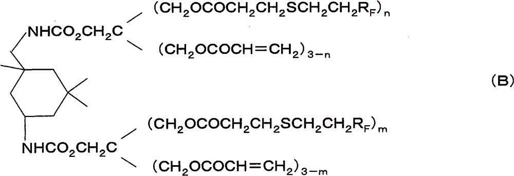
[0232]In a 500 ml reaction flask, 22.2 g (0.1 mole) of isophorone diisocyanate was added dropwise to 100 ml of MIBK (methyl isobutyl ketone) solution while gas bubbling at 25°C. Pentaerythritol triacrylate 59.6 g (0.20 mol) of MIBK 50ml solution. After completion of the dropwise addition, 0.3 g of dibutyltin dilaurate was added, followed by heating and stirring at 70° C. for 4 hours. After the reaction, the reaction solution was washed with 100 ml of 5% hydrochloric acid. After separating and collecting the organic layer, the solvent was distilled off under reduced pressure at 40° C. or lower to obtain 80.5 g of urethane acrylate as a colorless transparent viscous liquid. 40.8 g (0.05 mol) of the prepared urethane acrylate, 71.9 g (0.15 mol) of perfluorooctyl ethyl mercaptan, and 60 g of MIBK were put into a 200 ml reaction flask and homogenized. 1.0 g of triethylamine was ...
PUM
| Property | Measurement | Unit |
|---|---|---|
| particle size | aaaaa | aaaaa |
| particle size | aaaaa | aaaaa |
| thickness | aaaaa | aaaaa |
Abstract
Description
Claims
Application Information
 - R&D
- Intellectual Property
- Life Sciences
- Materials
- Tech Scout
- Unparalleled Data Quality
- Higher Quality Content
- 60% Fewer Hallucinations
Browse by: Latest US Patents, China's latest patents, Technical Efficacy Thesaurus, Application Domain, Technology Topic, Popular Technical Reports.
© 2025 PatSnap. All rights reserved.Legal|Privacy policy|Modern Slavery Act Transparency Statement|Sitemap|About US| Contact US: help@patsnap.com


