Preparation method of stannous oxide polycrystalline film

A stannous oxide and thin film technology is applied in the field of preparation of stannous oxide polycrystalline thin films, which can solve the problems of high preparation requirements, complex preparation methods or processes, and increased preparation costs, and achieves reduced preparation difficulty and substrate pre-processing. The effect of simple processing technology and low cost

Inactive Publication Date: 2011-04-20
NINGBO INST OF MATERIALS TECH & ENG CHINESE ACADEMY OF SCI
View PDF0 Cites 9 Cited by
  • Summary
  • Abstract
  • Description
  • Claims
  • Application Information

AI Technical Summary

Problems solved by technology

[0006] Above-mentioned preparation method or technique are complicated, and the source material (SnO 2 target or single-phase SnO target), the requirements for the preparation of the substrate used and the operation requirements for the equipment are relatively high, so the preparation is difficult, and it also leads to an increase in the preparation cost

Method used


Image

  • Preparation method of stannous oxide polycrystalline film
  • Preparation method of stannous oxide polycrystalline film
  • Preparation method of stannous oxide polycrystalline film

Examples


Embodiment 1

[0024] In this embodiment, quartz glass is used as the substrate to realize the preparation of the SnO polycrystalline thin film, including the following steps.

[0025] First, a quartz glass substrate is provided. The quartz glass substrate provided in this step is a non-single crystal substrate.

[0026] The quartz glass substrate is then cleaned. The specific method of cleaning may be to use acetone, ethanol and deionized water to perform ultrasonic cleaning on the quartz glass substrate for 15 minutes each.

[0027] Next, the cleaned quartz glass substrate and SnO 2 The ceramic sintering evaporation material is placed at the corresponding position of the electron beam evaporation coating equipment. The electron beam evaporation coating equipment can be, for example, the electron beam evaporation coating equipment of the model MUE-ECO of Japan ULVAC Company.

[0028] Heat the quartz glass substrate to 350°C, and set the background vacuum to 5×10 -6 Pa. Electron beam b...

Embodiment 2

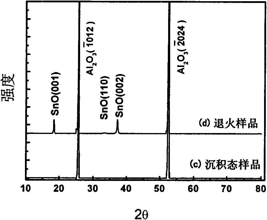
[0032] In this embodiment, the substrate is changed to a single crystal sapphire substrate, while other process steps and process parameters are the same as in Embodiment 1.

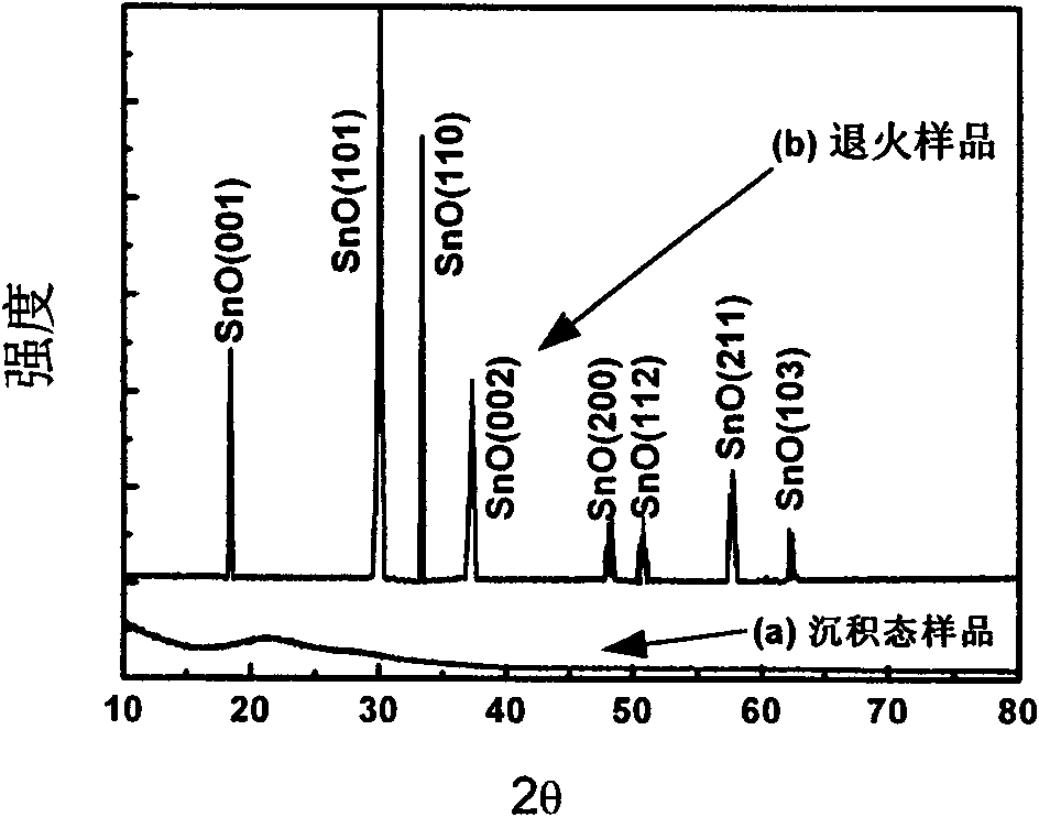
[0033] In this example, the prepared SnO x The film sample is called (c) as-deposited sample, and the prepared SnO polycrystalline film sample is called (d) annealed sample.

[0034] The above (c) as-deposited sample and (d) annealed sample were characterized by X-ray diffraction spectrum (XRD), and the results are as follows: figure 2 shown. figure 2 SnO is not observed in the XRD spectrum of the (c) deposited state sample on the sapphire substrate of the present embodiment X Any diffraction peaks of (1 figure 2 In the XRD spectrum of the (d) annealed sample on the sapphire substrate in this embodiment, the diffraction peaks of SnO are observed, and all peaks can be found in the XRD standard card (06-0395) of SnO corresponding to the diffraction peaks , that is to say, the annealed sapphire film in t...

Embodiment 3

[0041] In this example, SnO x The thin film deposition step is carried out at a vacuum degree of 2×10 -4 It is carried out in a vacuum environment of Pa, and the deposition rate is 0.04nm / s. For SnO x The film was thermally annealed at a vacuum of 2×10 -4 Pa vacuum environment. Other processing steps and conditions are identical with embodiment 1.


PUM


Abstract

The invention relates to a preparation method of polycrystalline stannous oxide film. The invention utilizes stannic oxide (SnO2) as the evaporation material and electron beam evaporation equipment. The preparation method comprises the following steps: preparing SnOx (x is bigger than 1 and smaller than 2) amorphous film at a low temperature firstly, conducting vacuum annealing treatment at high temperatures, therefore obtaining stannous oxide (SnO) polycrystalline film. The invention is advantageous in that: the preparation method is simple and controllable, in addition a large-area uniform film can be formed on a substrate such as quartz glass, and the film-forming repeatability is good. Stannous oxide is p-type electric conductive oxide and can be used to prepare oxide-based photoelectron and electron device.

Description

technical field [0001] The invention relates to a method for preparing a metal oxide polycrystalline film, in particular to a method for preparing a tin oxide polycrystalline film. Background technique [0002] New electronic thin films are the material basis for emerging interdisciplinary subjects and products such as contemporary microelectronics, optoelectronics, magnetoelectronics, solar energy utilization, and sensors, and have widely penetrated into various fields of contemporary technology. Among them, the transparent oxide thin film (Transparent Oxide thin Film) has the characteristics of simple preparation process and multi-functionality, especially the application of transparent oxide thin-film transistor (Transparent oxide Thin-Film Transistor, TTFT), which has been attracting attention in recent years. s concern. Thin film field effect transistors using transparent oxide as the channel layer have achieved field effect mobility greater than 10cm 2 V - 1s -1 , ...

Claims


Application Information

Patent Timeline
Patent Type & Authority Applications(China)
IPC IPC(8): C23C14/30C23C14/08C23C14/58H01L21/203H01L21/324
Inventor 曹鸿涛梁凌燕刘志敏
Owner NINGBO INST OF MATERIALS TECH & ENG CHINESE ACADEMY OF SCI
Why Eureka
Try Eureka