
Photoluminescent nano particle as well as preparation method and application thereof

A technology of fluorescent nanoparticles and particles, which is applied in the field of fluorescent nanoparticles based on rare earth complex fluorescent dyes and its preparation, can solve the problems of fluorescence quenching, large particle size, strong scattering signal, etc., and achieve large Stocks shift and excellent luminescence performance , the effect of high luminous brightness

Inactive Publication Date: 2011-07-27
PEKING UNIV
View PDF4 Cites 18 Cited by
  • Summary
  • Abstract
  • Description
  • Claims
  • Application Information

AI Technical Summary

Problems solved by technology

However, nanoparticles based on common hydrophobic polymers are prone to agglomeration in aqueous solution, and their particle size is large, and the scattering signal is strong.
The silica matrix also often leads to the leakage of fluorescent dyes in the formed nanoparticles due to the difficulty in forming a dense encapsulation layer
[0007] The inventors of the present invention have used the reported rare earth complex-based fluorescent nanoparticle synthesis method (such as microemulsion polymerization, alkoxysilane hydrolysis embedding method, etc.), to design and synthesize Eu(tta) 3 Rare earth complexes with excellent visible and near-infrared light-excited luminescent properties such as dpbt are nano-embedded to synthesize new rare earth complex-based fluorescent nanoparticles, but it is difficult to obtain satisfactory results.
The main reason is that the coordination between ligands and rare earth ions of such rare earth complexes with excellent visible light and near-infrared excitation and luminescence properties is weak, and the usual complex embedding methods easily lead to ligand dissociation or fluorescence quenching. Destroyed, lost the original optical properties

Method used


Image

  • Photoluminescent nano particle as well as preparation method and application thereof
  • Photoluminescent nano particle as well as preparation method and application thereof
  • Photoluminescent nano particle as well as preparation method and application thereof

Examples


Embodiment 1

[0064] Embodiment 1, take methacrylic acid-methyl methacrylate copolymer as matrix material based on Eu(tta) 3 Preparation of fluorescent nanoparticles of dpbt

[0065] Get methacrylic acid-methyl methacrylate copolymer (number average molecular weight is 50,000, carboxyl group mass fraction: 1.0%) and Eu(tta) 3 dpbt (structure shown in formula VII) is dissolved in acetone to obtain acrylic acid-methyl methacrylate copolymer concentration of 1g / L, Eu(tta) 3 dpbt concentration of 0.1g / L acetone solution. Under stirring, 20 mL of the above solution was added dropwise to 80 mL of water, and the stirring was continued for 10 min. Acetone was evaporated at 30° C., centrifuged at 25,000 rpm (50,000 G), and the resulting precipitate was redispersed in pure water to obtain a sol of fluorescent nanoparticles containing carboxyl groups on the surface.

[0066]

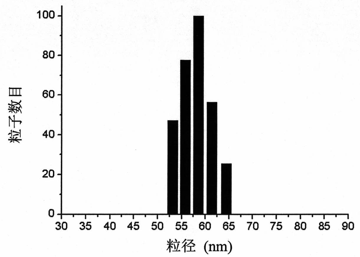
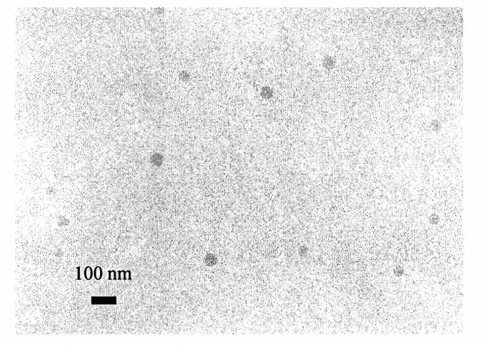
[0067] Such as figure 1 As shown, the dynamic light scattering test results show that the average particle size of the ...

Embodiment 2

[0070] Embodiment 2, taking styrene-methacrylic acid block copolymer as matrix based on Eu(tta) 3 Preparation of fluorescent nanoparticles of dpbt

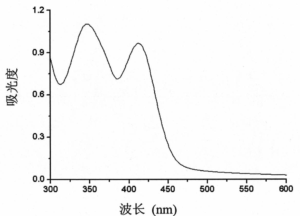
[0071] The copolymer in example 1 is replaced by styrene-methacrylic acid block copolymer (number average molecular weight is 100,000, styrene group mass fraction: 40%, carboxyl group mass fraction: 25%), this block copolymer The concentration is 10g / L, and the centrifugal speed is changed to 4000rpm, and the Eu(tta) based Eu(tta) 3 Fluorescent nanoparticles of dpbt. Such as Image 6 As shown, the dynamic light scattering test results show that the average particle size of the prepared fluorescent nanoparticles is 100 nm, and the particle size distribution range is 85-115 nm. Figure 7 It is the ultraviolet-visible absorption spectrum of the prepared fluorescent nanoparticle sol. It can be seen from the figure that the fluorescent nanoparticle has an absorption peak at 415nm in the visible region, and the scattering of visible ...

Embodiment 3

[0072] Embodiment 3, taking methacrylic acid-methyl methacrylate copolymer as matrix based on Eu(nta) 3 Preparation of fluorescent nanoparticles of bpt

[0073] Methacrylic acid-methyl methacrylate copolymer (number average molecular weight: 5,000, carboxyl group mass fraction: 10%) and Eu(nta) 3 bpt (structure shown in formula VIII, its preparation method is shown in Example 14) was dissolved in methanol, and the concentration of methacrylic acid-methyl methacrylate copolymer was prepared as 0.02g / L, Eu(tta) 3 bpt concentration is 2 x 10 -3 g / L methanol solution. With stirring, 25 mL of the above solution was added dropwise to 75 mL of water, and the stirring was continued for 10 min. Methanol was removed by vacuum rotary evaporation at 4° C., centrifuged, and the resulting precipitate was redispersed in pure water to obtain a sol of fluorescent nanoparticles containing carboxyl groups on the surface.

[0074] Figure 9 It is the ultraviolet-visible absorption spectrum o...


PUM

PropertyMeasurementUnit
particle diameteraaaaaaaaaa
concentrationaaaaaaaaaa
particle sizeaaaaaaaaaa

Abstract

The invention discloses a photoluminescent nano particle as well as a preparation method and an application thereof. The photoluminescent nano particle is composed of a carboxyl-containing copolymer matrix material and a rare earth fluorescent dye dispersed in the matrix material. The preparation method of the fluorescent nano particle comprises the following steps: dissolving the rare earth compound fluorescent dye and the copolymer in an organic solvent which is capable of being miscible with water; and adding the solution in water, so that the fluorescent nano particle is formed by utilizing a coprecipitation-self assembly process. The fluorescent nano particle has the advantages of excellent long wave excitation luminescence property and good stability, and has a surface carboxyl group for coupling biomolecules. A biological probe based on the fluorescent nano particle has a wide application prospect in the aspects of high-sensitivity fluorescent immunoassay, biological imaging and the like.

Description

technical field [0001] The present invention relates to a class of photoinduced nanoparticles and a class of rare earth complex fluorescent dyes that can be used to prepare such nanoparticles and their preparation methods and applications, especially a class of fluorescent nanoparticles based on rare earth complex fluorescent dyes and their preparation Methods and applications. Background technique [0002] Fluorescent probes of rare earth complexes have important applications in the fields of biological imaging, DNA detection, and immunoassay. Its main advantage is that rare earth complexes have the characteristics of longer luminescence lifetime, larger Stokes shift, and sharp line emission peaks. These characteristics make it possible to effectively filter background signal interference through time-resolved technology in biochemical analysis, achieve high-sensitivity detection, and avoid the biosafety problems caused by traditional radiolabeling methods. [0003] Since...

Claims


Application Information

Patent Timeline
Patent Type & Authority Applications(China)
IPC IPC(8): C07F5/00C09K11/06C08L101/08C08K5/00G01N33/52
CPCG01N2458/40C07F5/003C09K11/06C07D403/14G01N33/587C09K2211/182G01N33/52
Inventor 王远邵光胜韩荣成马严薛富民
Owner PEKING UNIV
Learn More