

Surface-electrode-technology-based high-throughput cell electrofusion chip device
A surface electrode, high-throughput technology, applied in the field of cell electrofusion, can solve problems such as cell clogging
- Summary
- Abstract
- Description
- Claims
- Application Information
AI Technical Summary
Problems solved by technology
Method used
Image

Examples
Embodiment 1
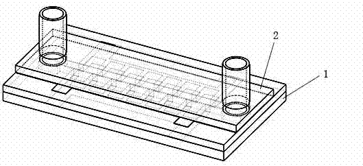
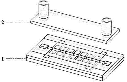
[0041] see figure 1 , figure 2 with image 3 , the high-throughput cell electrofusion chip device based on surface electrode technology consists of a high-throughput cell electrofusion chip 1 and a cover sheet 2 with a sample inlet and outlet conduit.
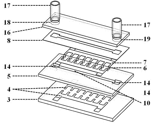
[0042] see image 3 , the high-throughput cell electrofusion chip 1 consists of a quartz base layer 3 , a polymer microchannel layer 5 and a top protective layer 8 from bottom to top.
[0043] Bottom comb-shaped microelectrode array 4, side wall surface electrode layer 6, top comb-shaped micro-electrode array layer 7, which is characterized in that the bottom comb-shaped micro-electrode array layer 4, side wall electrode layer 6 and top comb-shaped micro-electrode array layer 7 Electrically communicated and form a side wall surface electrode array 9 with a “sandwich” structure, combined with the quartz base layer 3 and the polymer microchannel layer 5 to form a smooth flow channel 10 .
[0044] The underlying comb-shaped mi...
Embodiment 2
[0051] Embodiment 2: the using method of this device
[0052] In the experiment, a micropump can be used to inject the cell suspension into the chip from the injection port 18 in Example 1. When the cell suspension flows through the microchannel 10, a sine wave electrical stimulation signal is loaded through the bonding point 13 or 15, A non-uniform gradient electric field will be formed between the microelectrodes on the opposite side walls, and the two cells between the microelectrodes will line up under the action of dielectrophoretic force. After the queuing is completed, a square wave pulse sequence signal is applied, and the queuing cell pairs will complete the process of cell electroporation-cell electrofusion under the action of a high-intensity pulse electric field between the microelectrodes. After the cell electrofusion process is completed, the micropump is used to inject the cell culture solution, and the cells in the microchannel flow out through the microchannel...
Embodiment 3
[0053] Example 3: Fabrication of high-throughput cell electrofusion chip device
[0054] Using MEMS processing technology, the processing technology is as follows:
[0055] A. Clean the quartz glass sheet;
[0056] B. Put the quartz glass sheet in the evaporation furnace, and evaporate and deposit to form 2000 the gold film;
[0057] C. Spin-coat AZ4620 on the surface of the gold film, and form the same pattern as the underlying microelectrode array structure after exposure and development;
[0058] D. Place the quartz glass sheet in gold etching solution and HF etching solution successively to remove excess gold film and form the underlying microelectrode array structure;
[0059] E. Acetone removes the residual AZ4620 on the surface of the underlying microelectrode array structure;
[0060] F. cleaning;
[0061] G. Spin-coat PI7510 on the surface of the quartz glass sheet, expose and develop to form a polymer microchannel layer, and place it in a curing oven to cure PI...
PUM
| Property | Measurement | Unit |
|---|---|---|
| Thickness | aaaaa | aaaaa |
Abstract
Description
Claims
Application Information