Copper-clad laminate-based method for micro-removing copper film from selected area by assistance of laser

A laser-assisted, copper-clad laminate technology, applied in the field of micro-machining, can solve the problems of complex operation, high cost, environmental pollution, etc., and achieve the effects of good controllability, high precision and high efficiency

Inactive Publication Date: 2011-09-28
BEIJING UNIV OF TECH
View PDF3 Cites 28 Cited by
  • Summary
  • Abstract
  • Description
  • Claims
  • Application Information

AI Technical Summary

Problems solved by technology

[0007] The above methods all have common shortcomings: complex operation, high cost, long cycle and environmental pollution, can not prepare random graphics and the accuracy is limited by the template
[0008] Due to the large difference between the melting point of the FCCL substrate and the copper foil, it is difficult to completely remove the copper foil without damaging the substrate by direct laser etching, especially if it is necessary to etch a larger-sized pattern.

Method used


Image

  • Copper-clad laminate-based method for micro-removing copper film from selected area by assistance of laser
  • Copper-clad laminate-based method for micro-removing copper film from selected area by assistance of laser

Examples


example 1

[0036] The example of the present invention selects a fiber laser with small volume, good beam quality, and convenient processing, and the laser motion control system adopts a scanning vibrating mirror; the copper clad plate is a flexible copper clad plate with a base film of 70 μm polyester film plated with 18 μm copper foil; selects 5% hydrogen peroxide A mixed solution of 15% hydrochloric acid is used as an etchant; a quick-drying thermoplastic acrylic aerosol paint is selected as a coating; PHOTOSHOP software is selected as a drawing software; a ring with an outer diameter of 10mm, an inner diameter of 6mm, and a regular five-pointed star with a size of 10mm are selected as the removal agent. Pattern; use ultrasound to remove final paint.

[0037]This example is carried out as follows: spray the quick-drying thermoplastic acrylic aerosol paint evenly on the copper foil, and after the spray paint is dry, place the copper clad laminate on the focal plane of the laser vibratin...

example 2

[0039] The example of the present invention selects the small CO with the maximum power of 30W 2 The laser and the laser motion control system adopt three-dimensional numerical control machine tools; the copper-clad laminate adopts a base film of 70 μm polyester film and a flexible copper-clad laminate plated with 18 μm copper foil; selects 50% ferric chloride solution as the etchant; selects silica gel as the coating; selects PHOTOSHOP software is used as the drawing software; a ring with an outer diameter of 10mm and an inner diameter of 6mm, and a regular five-pointed star with a size of 10mm are selected as the removal pattern; ultrasonic waves are used to remove the final paint.

[0040] This example is carried out as follows: apply silica gel evenly on the copper foil, and after the silica gel dries, place the copper clad laminate on the focal plane of the laser lens on the workbench and fix it with a fixture; draw an outer diameter of 10mm in the PS software , a ring wi...


PUM


Abstract

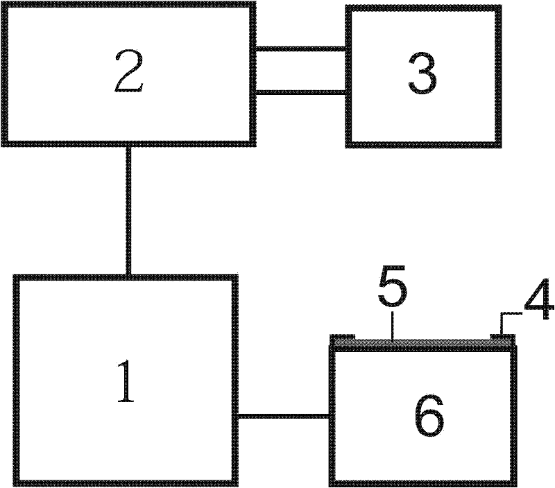
The invention discloses a copper-clad laminate-based method for micro-removing copper film from a selected area by assistance of laser, belonging to the field of micromachining. The method comprises the following steps of: applying a layer of coating material on the surface of a copper foil of the copper-clad laminate; making a pattern to be removed through drawing software; respectively connecting a laser with a laser motion control system and a computer, wherein laser parameters and a laser motion path are controlled through laser control software; placing and clamping the coated copper-clad laminate on a processing platform, and keeping a coated surface of the copper-clad laminate and the focal point of a laser beam within a same plane; importing the pattern to be removed into the laser control software, positioning the pattern in the position where the copper film is required to be removed by indicating light, and adjusting the laser parameters so that the laser beam acts on the copper-clad laminate for selectively removing the coated layer; placing the scanned copper-clad laminate into an etching agent to be etched; and putting and rinsing the etched sample in clean water to remove the coating. The invention has the advantages of high precision and efficiency, good controllability, and controllable shape of the selected area, and can realize FPC (Flexible Printed Circuit)wiring and masking as well as manufacturing of exquisite handicraft articles.

Description

technical field [0001] The invention relates to a method for removing a copper film based on a laser-assisted selective area selection of a copper-clad laminate, which can remove copper foil with a controllable pattern on a copper-clad laminate material, and belongs to the field of micromachining. Background technique [0002] The laser has the characteristics of good monochromaticity, good coherence, and good directionality, and it is easy to connect with a computer to realize automatic control. Therefore, laser processing has been widely used. The laser focused by the lens has a very high energy density at the focal plane, which can be used for drilling, cutting, welding, scribing, heat treatment, marking, cleaning and other processing of materials. High-energy photons can also initiate or control photochemical reactions, and realize photochemical reaction processing such as laser etching, photochemical deposition, and stereolithography. Laser processing has no contact w...

Claims


Application Information

Patent Timeline
Patent Type & Authority Applications(China)
IPC IPC(8): H05K3/06B23K26/36
Inventor 陈继民袁建文
Owner BEIJING UNIV OF TECH
Why Eureka
Try Eureka