Carbonizer for continuously synthesizing calcium carbonate and production method of calcium carbonate

A calcium carbonate and carbonizer technology, applied in the direction of calcium carbonate/strontium/barium, nanotechnology, etc., can solve the problems of wide particle size distribution, large fluctuation range of average particle size, high energy consumption in intermittent production, and easy to achieve. The effect of automated production control, narrow particle size distribution, and short residence time

Inactive Publication Date: 2013-05-15
连州市凯恩斯纳米材料有限公司
View PDF3 Cites 3 Cited by
  • Summary
  • Abstract
  • Description
  • Claims
  • Application Information

AI Technical Summary

Problems solved by technology

There are the following problems and deficiencies in the preparation of fine particle calcium carbonate with this synthesis method and equipment: (1) the particle size distribution range of the produced product is wide; (2) the average particle size fluctuation range between different batches is large; (3) the reaction process The encapsulation phenomenon is easy to occur in the medium, which eventually leads to the product returning to alkali and affecting the product quality; (4) The two processes of nucleation and crystal growth are not separated, and it is difficult to control the process conditions to obtain solid particles of uniform size; (5) The production process Lower temperature operation is required (generally lower than 25°C), and the energy consumption is high; (6) The carbonization reaction time is long, the energy consumption of intermittent production is high, the output is low, and the CO 2 low utilization

Method used


Image

  • Carbonizer for continuously synthesizing calcium carbonate and production method of calcium carbonate
  • Carbonizer for continuously synthesizing calcium carbonate and production method of calcium carbonate

Examples


Embodiment 1

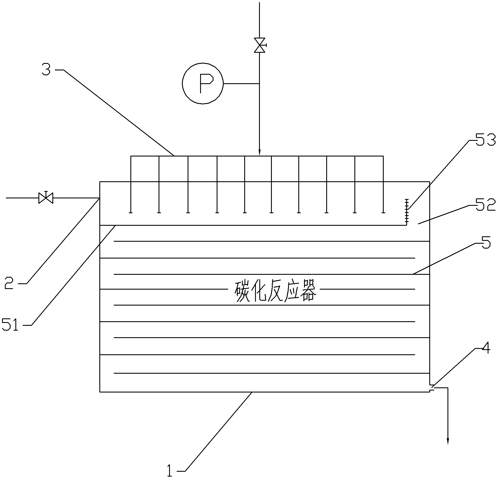
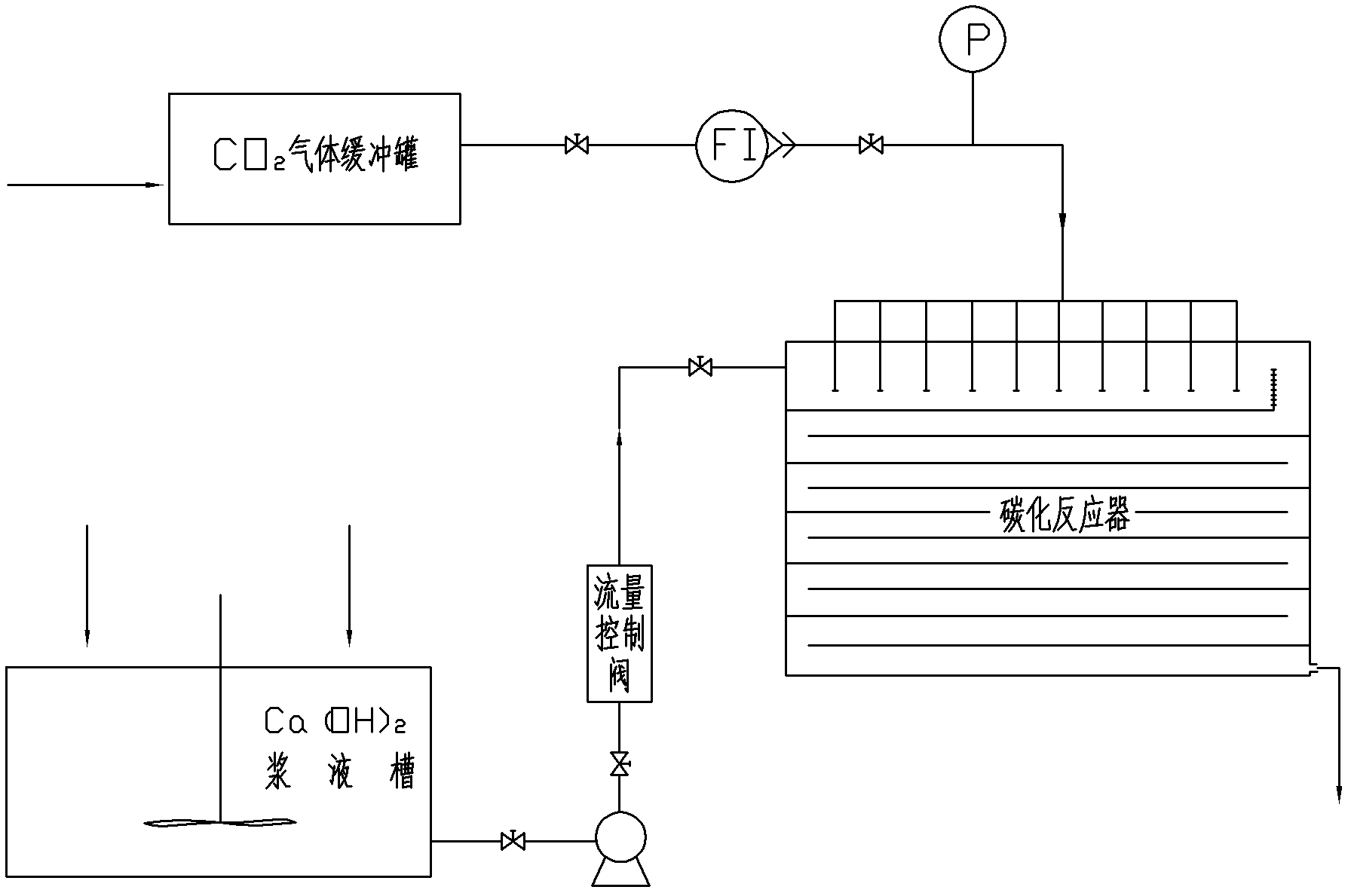
[0033] Such as process flow diagram figure 2 shown, to the CO 2 The buffer tank is fed with purified lime kiln gas with a volume concentration of 28%, namely CO 2 (The same below), to Ca(OH) 2 Ca(OH) 2 Ca(OH) with a concentration of 8% and a temperature of 25°C to 26°C 2 Slurry, start stirring and add 0.2% Ca(OH) by weight 2Calculate citric acid; It is 0.2MPa kiln gas with a gauge pressure of 0.2MPa to feed the carbonization reactor with a flow rate of 18 cubic meters / minute, and then pump Ca(OH) into the carbonization reactor with a flow rate of 20 cubic meters / hour. 2 Slurry, pumped Ca(OH) 2 Serum in as figure 2 The flow of the bubbling carbonized layer shown in the flow process has a carbonization reaction with the kiln gas sent from the kiln gas distribution pipe, flows to the other end and overflows from the top of the sieve plate or sieve plate to the next layer of trays, and continues to flow from the top of the sieve plate. The kiln gas flowing into the tr...

Embodiment 2

[0035] to CO 2 The buffer tank is fed with purified lime kiln gas with a volume concentration of 28%, to Ca(OH) 2 Slurry tank into Ca(OH) 2 Ca(OH) with a concentration of 8% and a temperature of 30°C to 31°C 2 Slurry, start stirring and add 0.5% Ca(OH) by weight 2 Calculating magnesium sulfate; first feed the kiln gas with a gauge pressure of 0.15MPa to the carbonization reactor with a flow rate of 36 cubic meters per minute, and then pump Ca(OH) into the carbonization reactor with a flow rate of 30 cubic meters per hour 2 Slurry, pumped Ca(OH) 2 The slurry flows in the bubbling carbonization layer shown in the figure. During the flow process, it undergoes carbonization reaction with the kiln gas sent from the kiln gas distribution pipe. After flowing to the other end, it overflows from the top of the sieve plate or sieve plate to the next layer of plate, and continues The carbonization reaction occurs with the kiln gas flowing into the tray layer from the top of the s...

Embodiment 3

[0037] To the CO 2 The buffer tank is fed with purified lime kiln gas with a volume concentration of 28%, to Ca(OH) 2 Slurry tank into Ca(OH) 2 Ca(OH) with a concentration of 8% and a temperature of 40°C to 45°C 2 Slurry; first feed the kiln gas with a gauge pressure of 0.12MPa to the carbonization reactor at a flow rate of 52 cubic meters per minute, and then pump Ca(OH) into the carbonization reactor at a flow rate of 40 cubic meters per hour 2 Slurry, pumped Ca(OH) 2 The slurry flows in the bubbling carbonization layer shown in the figure. During the flow process, it undergoes carbonization reaction with the kiln gas sent from the kiln gas distribution pipe. After flowing to the other end, it overflows from the top of the sieve plate or sieve plate to the next layer of plate, and continues The carbonization reaction occurs with the kiln gas flowing into the tray layer from the top of the sieve plate in the same direction, and finally flows out from the bottom of the carb...


PUM

PropertyMeasurementUnit
particle diameteraaaaaaaaaa

Abstract

The invention relates to a carbonizer for continuously synthesizing calcium carbonate and a production method of calcium carbonate, an input port of calcium hydroxide, an input port of carbon dioxide are provided on the body of the carbonizer, a discharge port is provided at the bottom of the carbonizer, the input port of calcium hydroxide and the input port of carbon dioxide are positioned at the top of the carbonizer body, the transverse trays with displacement from each other are uniformly arranged from the lower part to the bottom of two input ports in the body of the carbonizer, a layout of a S shape backflow baffle plate or a snaky shape backflow baffle plate is used between the adjacent trays. The calcium hydroxide slurry is a fluid suspension, and enables an equidirectional flow with carbon dioxide on the transverse trays between the trays, the calcium hydroxide slurry enters to the next tray from an outlet, three phases of gas, liquid and solid phase are reacted to generate precipitated calcium carbonate, the reacted material-carbonized boiled slurry is flowed out from the outlet of lower part of the reactor. The product has the advantages of adjustable particle size, narrow grain size distribution and stable quality, dispersibility, stability and alkali efflorescence are improved; the invention has the advantages of less equipment investment, short reaction time, less energy consumption, low cost, and the product enables continuous production.

Description

technical field [0001] The invention relates to a method for continuously synthesizing calcium carbonate and equipment thereof, in particular to a method for continuously carbonizing and synthesizing calcium carbonate and a carbonization reactor used therein. Background technique [0002] Precipitated calcium carbonate is an important inorganic powder material. At present, the industrial production processes of precipitated calcium carbonate at home and abroad mainly include: intermittent bubbling carbonization method, continuous spray multi-stage carbonization method, continuous bubbling carbonization method, supergravity reaction crystallization method, vertical sieve plate Tower carbonization method, internal circulation carbonization tower preparation method. Among them, the intermittent bubbling carbonization method and the continuous bubbling carbonization method are widely used to prepare fine particle calcium carbonate. 2 The gas is injected with Ca(OH) 2 T...

Claims


Application Information

Patent Timeline
Patent Type & Authority Patents(China)
IPC IPC(8): C01F11/18B82Y40/00
Inventor 晏中华熊维湘胡利康左卫民郑庆民马跃东王秀伟
Owner 连州市凯恩斯纳米材料有限公司
Why Eureka
Try Eureka