
Automobile fuel oil evaporative rubber tube with composite structure and manufacturing method for automobile fuel oil evaporative rubber tube

A composite structure and manufacturing method technology, which is applied in the direction of hoses, pipes, pipes/pipe joints/pipe fittings, etc., can solve the problems of accelerating the aging of the outer rubber hose material, unfavorable environmental protection requirements for fuel emissions, and poor fuel resistance of the outer rubber. Achieve the effect of saving production cost, improving enterprise operating efficiency, and good fuel resistance

Inactive Publication Date: 2012-04-18
宁波丰茂汽车零部件有限公司
View PDF6 Cites 14 Cited by
  • Summary
  • Abstract
  • Description
  • Claims
  • Application Information

AI Technical Summary

Problems solved by technology

[0004] 2. The fuel permeability of the material is high, which is not conducive to the environmental protection requirements of fuel emissions
[0005] 3. Fuel penetrates into the outer layer of the rubber hose, and the aging of the outer rubber hose material is accelerated due to the poor fuel resistance of the outer rubber

Method used


Image

  • Automobile fuel oil evaporative rubber tube with composite structure and manufacturing method for automobile fuel oil evaporative rubber tube
  • Automobile fuel oil evaporative rubber tube with composite structure and manufacturing method for automobile fuel oil evaporative rubber tube
  • Automobile fuel oil evaporative rubber tube with composite structure and manufacturing method for automobile fuel oil evaporative rubber tube

Examples


Embodiment 1

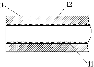
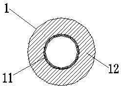
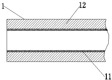
[0047] Embodiment one, such as Figure 1 to Figure 2 As shown, a composite structure automotive fuel evaporation rubber hose of the present invention includes a rubber hose body 1, and the rubber hose body 1 is an inner tube rubber made of fluorine rubber containing bisphenol vulcanizing agent, magnesium oxide, calcium hydroxide, carbon black and accelerator The layer 11 is composed of the outer tube rubber layer 12 made of chloroether rubber containing vulcanizing agent, carbon black, plasticizer, magnesium oxide and anti-aging agent, and the inner tube rubber layer 11 and the outer tube rubber layer 12 are integrated through a compound extruder Adhesive compound extrusion. Also contain stearic acid and calcium carbonate in its outer tube rubber layer 12.

[0048] A kind of manufacture method of composite structure automobile fuel evaporation hose of the present invention comprises the following steps:

[0049] step 1, The sizing materials of the inner and outer tube rubbe...

Embodiment 2

[0076] Embodiment 2, a composite structure automotive fuel evaporation rubber hose of the present invention, including a rubber hose body 1, the rubber hose body 1 is composed of an anti-permeation fluorine rubber inner tube rubber layer 11 and an ECO outer tube rubber layer 12 through a T-shaped compound extruder. Adhesive compound extrusion. Its manufacturing method comprises the following steps:

[0077] step 1, The sizing materials of the inner and outer tube rubber layers are sent to the internal mixer for mixing respectively according to the following parts by weight, and the parts by weight of each raw material of the rubber layer of the inner tube are:

[0078] Fluorine rubber 100 parts by weight

[0079] Bisphenol AF vulcanizing agent 2.5~4.0 parts by weight

[0080] Accelerator BPP 0.2~0.4 parts by weight

[0081] Magnesium oxide 2.0~5.0 parts by weight

[0082] Calcium hydroxide 5.0~8.0 parts by weight

[0083] Carbon black N990 20.0-40.0 parts by weight

[0...

Embodiment 3

[0104] Embodiment 3, a composite structure automotive fuel evaporation hose of the present invention, including a hose body 1, the hose body 1 is integrally glued and compounded by an inner tube rubber layer 11 and an outer tube rubber layer 12 through a T-shaped compound extruder. Its manufacturing method comprises the following steps:

[0105] step 1, The sizing materials of the inner and outer tube rubber layers are sent to the internal mixer for mixing respectively according to the following parts by weight, and the parts by weight of each raw material of the rubber layer of the inner tube are:

[0106] Fluorine rubber 100 parts by weight

[0107] 3 parts by weight of bisphenol AF vulcanizing agent

[0108] Accelerator BPP 0.3 parts by weight

[0109] Magnesium oxide 3 parts by weight

[0110] Calcium hydroxide 6 parts by weight

[0111] Carbon black N990 30 parts by weight

[0112] The parts by weight of each raw material of its outer tube rubber layer are:

[0113...


PUM

PropertyMeasurementUnit
Burst strengthaaaaaaaaaa

Abstract

The invention discloses an automobile fuel oil evaporative rubber tube with a composite structure and a manufacturing method for the automobile fuel oil evaporative rubber tube. The rubber pipe consists of an inner tube rubber layer made of fluororubber containing a bisphenol vulcanizer, magnesium oxide, calcium hydroxide, carbon black and a promoter and an outer tube rubber layer made of epichloro-hydrin rubber containing a vulcanizer, the carbon black, a plasticizer, the magnesium oxide and an anti-aging agent, and the inner tube rubber layer and the outer tube rubber layer are glued integrally and extruded in a composite mode by a composite extruding machine. The manufacturing method comprises the following steps of: mixing sizing materials of an inner tube and an outer tube in an internal mixer, passing through an open mill thinly, extruding a rubber tube blank from the composite extruding machine in a composite mode, cutting under the condition of a fixed length, vulcanizing by an evaporative cylinder, performing two-section vulcanization, cutting a head under the condition of the fixed length, and cleaning to obtain the evaporative rubber tube. The manufacturing method has an advanced process and high production efficiency and is low is manufacturing cost; and a finished product is low in fuel oil permeability, resistant to heat, aging and negative pressure and environment-friendly, and can meet the requirements of vehicular assembly.

Description

technical field [0001] The invention relates to the technical field of manufacturing a rubber hose, in particular to a fuel evaporation hose used in automobiles, in particular to a composite structure automobile fuel evaporation hose and a manufacturing method thereof. Background technique [0002] The automobile fuel evaporation hose is the connection channel connecting the upper cover of the fuel tank and the adsorption carbon tank. The fuel vapor evaporated in the fuel tank is transported to the carbon tank through the fuel evaporation hose and is absorbed by activated carbon. The fuel evaporation hose must be made of good fuel resistance, fuel Rubber hose with low permeability, heat resistance, aging resistance and negative pressure resistance. The material of the fuel evaporation hose in the prior art is generally a single-layer structure of nitrile rubber plus PVC material, or a structure in which nitrile rubber is used as an inner rubber layer, polyester fiber is used...

Claims


Application Information

Patent Timeline
IPC IPC(8): F16L11/04B29B7/00B29C47/36B29C35/04C08L27/12C08L71/00C08K13/02C08K3/22C08K3/04C08K3/26B29C48/09B29C48/21
CPCB29C47/065B29C47/0023B29C47/882B29C48/09B29C48/21B29C48/9115
Inventor 蒋亨雷
Owner 宁波丰茂汽车零部件有限公司
Learn More