Fluorescent optical fiber and production method thereof, and white light floodlight made from fluorescent optical fiber

A fluorescent optical fiber and lighting technology, which is applied to cladding optical fibers, lighting devices, optical waveguides and light guides, etc., can solve the problems of small light-emitting angle, different light, and high heat dissipation cost, so as to reduce heat dissipation cost, large light-emitting angle, and soft light. Effect

Inactive Publication Date: 2012-05-02
广东华燚光电科技有限公司 +4
View PDF0 Cites 3 Cited by
  • Summary
  • Abstract
  • Description
  • Claims
  • Application Information

AI Technical Summary

Problems solved by technology

There are many processes, high production costs, and a high defect rate. Due to subtle errors in the packaging process, each lamp chip will emit different light, which increases the difficulty of light distribution.
At the same time, because the LED lamp grain is a point light source, the light emitted is direct light. In order to meet the indoor and outdoor lighting needs, it is necessary to carry out light distribution once or twice, and use a lens or lampshade to disperse the light. When the luminous angle reaches an angle of 1-180°, the luminous flux will lose 5%-30% every time the light distribution is performed. The more times of light distribution, the greater the loss of luminous flux, and the higher the cost of light distribution. There will be problems such as glare and light spots, and the light angle is small, generally no more than 180°
In addition, because the LED lamp particles are concentrated together, the cost of heat dissipation is high, and these problems need to be solved

Method used


Image

  • Fluorescent optical fiber and production method thereof, and white light floodlight made from fluorescent optical fiber
  • Fluorescent optical fiber and production method thereof, and white light floodlight made from fluorescent optical fiber

Examples


Embodiment 1

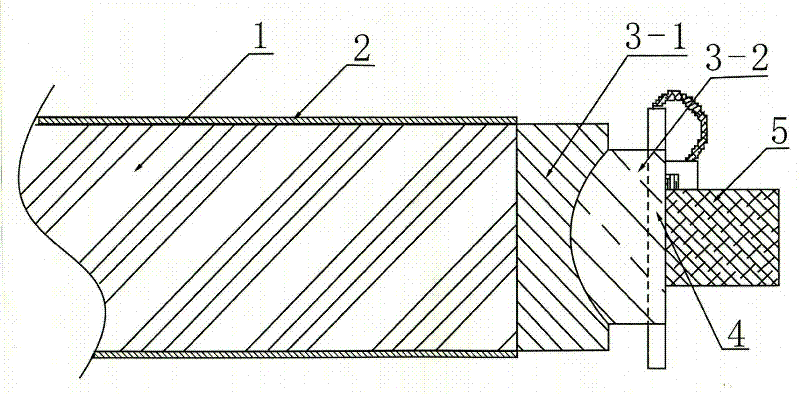
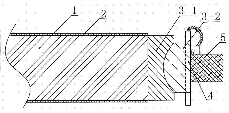
[0030] see figure 1 As shown, a fluorescent optical fiber has a phosphor layer 2 deposited on the surface of the optical fiber 1. The thickness of the phosphor layer 2 is 0.00001-0.001 mm. The optical fiber 1 can be a quartz optical fiber, or a plastic optical fiber or a plastic light guide column. . The phosphor powder of the phosphor powder layer 2 can adopt yellow phosphor powder or red phosphor powder or green phosphor powder or blue phosphor powder and mixture thereof, no matter adopt single-color phosphor powder or multi-color phosphor powder mixture, its color should be luminous with diode Only when the luminous colors of the modules match, can they emit white light directly.

Embodiment 2

[0032] One of the methods of depositing a layer of phosphor layer 2 on the surface of the optical fiber is:

[0033] (1) First clean the surface of the optical fiber with pure water to remove grease and other impurities, and then bake to remove water;

[0034] (2) Treat the optical fiber with mild plasma to increase the adhesion of the phosphor on the surface of the optical fiber. The treatment conditions are: vacuum degree 0.001-0.000001 mm Hg, time 1-10 minutes, and the protective gas is argon with a purity of 99.999%. gas;

[0035] (3) Put the optical fiber treated with mild plasma surface into a low-temperature horizontal magnetron sputtering machine for vacuum sputtering, the target material is phosphor powder, and the sputtering conditions are: vacuum degree is 0.001-0.000001 mm Hg, and the time is 1 - 10 minutes, use argon gas with a purity of 99.999% as the protective gas, and deposit phosphor molecules on the surface of the optical fiber by means of momentum transfer...

Embodiment 3

[0037] The second method of depositing a layer of phosphor layer 2 on the surface of the optical fiber is:

[0038] (1) Clean the optical fiber and bake to remove water;

[0039] (2) Treat the optical fiber with mild plasma to increase the adhesion of the phosphor on the surface of the optical fiber. The treatment conditions are: vacuum degree 0.001-0.000001 mm Hg, time 1-10 minutes, and the protective gas is argon with a purity of 99.999%. gas;

[0040] (3) Use a sublimation machine to further purify the phosphor powder at a temperature of 300-500°C for 30-100 minutes. Put the purified phosphor powder into the crucible chamber of a vacuum evaporation machine for evaporation for 1 -10 minutes, the degree of vacuum is 0.001-0.000001 mm Hg, the temperature is 100-1200° C., and the thickness of the obtained phosphor layer on the surface of the optical fiber is 0.00001-0.001 mm.


PUM


Abstract

The invention provides a fluorescent optical fiber, wherein a layer of fluorescent powder is deposited on the surface of an optical fiber. A production method of the fluorescent optical fiber comprises the following steps of: (1) firstly, cleaning the optical fiber, and removing water in a hot air drying way; (2) carrying out mild plasma treatment on the optical fiber, so that the adhesive force of the fluorescent powder to the surface of the optical fiber can be increased; and (3) performing vacuum sputtering by the means that the optical fiber which is performed by the mild plasma surface treatment is put into a low-temperature horizontal magnetron sputtering machine or performing evaporation plating or immersion plating by the means that the purified fluorescent powder is put into a vacuum evaporation plating machine, so that a layer of the fluorescent powder can be obtained on the surface of the optical fiber. A white light floodlight which is made from the fluorescent optical fiber is assembled by the means that the fluorescent optical fiber, an optical lens module, a diode luminescence module and a power source module are matched with one another. The production method of the fluorescent optical fiber is fewer in working procedures and low in cost. The white light floodlight which is made from the fluorescent optical fiber can directly emit white light without secondary light distribution, a lighting angle is approximate to 360 degrees, the light ray is soft, and the white light floodlight is free of glare and faculae.

Description

technical field [0001] The invention relates to the technical field of white light illumination lamps, in particular to a fluorescent optical fiber, a manufacturing method thereof, and a white light illumination lamp manufactured with the fluorescent optical fiber. Background technique [0002] In existing LED lighting fixtures, the light source module is usually composed of several LED lamp particles. If the lamp is to emit white light, one or more LED chips need to be packaged, that is, the phosphor powder and transparent packaging glue are fully mixed and placed on the LED chip. On the LED chip, the light of different colors emitted by the LED chip excites the phosphor, and finally mixes into white light. There are many processes, high production costs, and a high defect rate. Due to subtle errors in the packaging process, each lamp chip will emit different light, which increases the difficulty of light distribution. At the same time, because the LED lamp grain is a poin...

Claims


Application Information

Patent Timeline
Patent Type & Authority Applications(China)
IPC IPC(8): G02B6/02F21V5/04F21V8/00C03C25/00
Inventor 王培贤苏晋平
Owner 广东华燚光电科技有限公司
Why Eureka
Try Eureka