Anti-slip mat plate, its production method and application

An anti-slip mat and anti-slip technology, which is applied in the direction of chemical instruments and methods, layered products, glass/slag layered products, etc., can solve the problems of damage failure, small friction coefficient, and poor applicability, and achieve applicability improvement and friction coefficient Large, easy processing effect

Active Publication Date: 2012-05-09
QINGDAO CREATE ENVIRONMENT CONTROL TECH
View PDF2 Cites 12 Cited by
  • Summary
  • Abstract
  • Description
  • Claims
  • Application Information

AI Technical Summary

Problems solved by technology

Existing anti-skid pads are usually made of rubber materials, which generally have disadvantages such as easy aging, easy creep, not durable, and poor applicability
Another example is that the manhole cover installed on the road surface is often not tightly matched with the well seat. When the wheels run over it, it will bump and affect the safety of passing vehicles and pedestrians. Although this problem can be solved by using well-fitted manhole covers, due to the high cost, it cannot be popularized, so that incidents of manhole covers hurting people, cars, and disturbing people often occur, and they are also widely reported in the media. In practice, some The method of filling the gap between the well cover and the well seat with non-slip rubber backing plate can be used for a while, but rubber is a high elastic material with a small friction coefficient, a

Method used


Image

  • Anti-slip mat plate, its production method and application
  • Anti-slip mat plate, its production method and application
  • Anti-slip mat plate, its production method and application

Examples


Embodiment 1

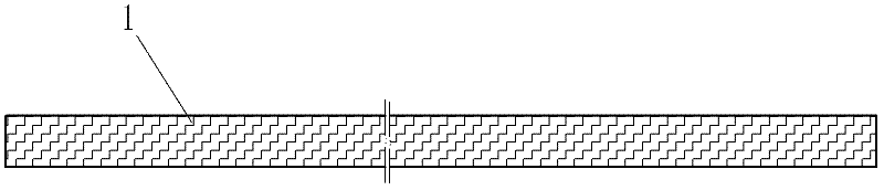
[0037] Such as figure 1 The shown anti-skid backing plate of the present invention comprises an anti-skid pad body 1, and the anti-skid pad body 1 is woven from jute material, and is soaked in modified asphalt in a molten state, wherein the modified asphalt is added with friction-enhancing material carbon black, so that The modified asphalt material is fully adsorbed in the pores of the jute fiber and in the weaving gap, and then the redundant modified asphalt material is discharged by steam heating method, and the anti-slip backing plate of the present invention is made after drying.

[0038] When utilizing the anti-slip backing plate of the present invention to do anti-slip treatment for equipment, it is only necessary to place the anti-slip backing plate between the equipment and the foundation, because the anti-slip backing body 1 of the anti-slip backing plate is woven by jute fibers, and its upper and lower contact surfaces have natural Rough surface, high adhesion modif...

Embodiment 2

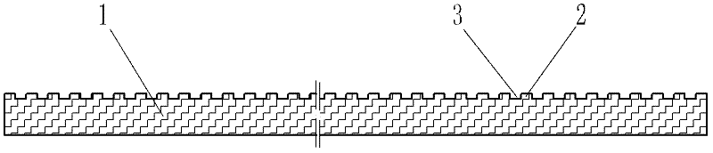
[0044] Such as figure 2 Shown anti-skid backing plate of the present invention, differs from embodiment one in that the anti-slip backing body 1 is woven from thread ropes made of sisal fibers. It is particularly pointed out that in order to improve the elasticity of the anti-slip backing plate, the When making the cord, a certain proportion of high elastic nylon fiber is also mixed into the sisal fiber. Then soak it with adhesive material, the adhesive material is mixed by emulsified asphalt, acrylic acid and cement, gypsum, mica powder and talcum powder, and rosin, a friction enhancing material, is added to make the adhesive material fully adsorbed into the pores of the fiber material and woven gap, and then mechanically extrude the excess adhesive material, and after drying, use a press to press and compact to obtain the anti-slip backing plate of the present invention. The slots 3 are arranged at intervals.

[0045] Since the surface of the anti-slip mat body 1 is provi...

Embodiment 3

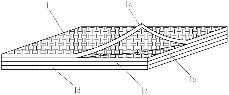
[0049] Such as image 3 The difference between the shown anti-slip backing plate of the present invention and the first embodiment is that the anti-slip mat body 1 is formed by laminating sub-anti-slip mat bodies 1a, 1b, 1c, and 1d. The sub-anti-skid mats 1a, 1b, 1c, 1d are respectively woven by wire ropes made of glass fibers, and soaked in emulsified asphalt, so that the floated asphalt materials are fully absorbed into the pores of glass fibers and the weaving gaps of wire ropes , and then squeeze out the excess emulsified asphalt material with a pressure roller and let it dry.

[0050] The advantage of this type of anti-slip pad is that the total thickness of the anti-slip pad can be controlled by changing the number of sub-anti-slip pads. In particular, each sub-anti-slip pad body in this anti-slip backing plate has independent and same anti-slip performance as the whole, so even if the sub-anti-slip pads are peeled off, the overall anti-slip performance will not be affe...


PUM

PropertyMeasurementUnit
Surface friction coefficientaaaaaaaaaa

Abstract

The invention relates to an anti-slip mat plate, which is characterized in that an anti-slip mat body is formed by spinning or weaving natural fibers or artificial fibers with good durability and tensile performance, and interior pores of the fibers are infiltrated with an adhesive material or the surfaces of the fibers are attached with the adhesive material. The anti-slip mat plate of the invention adopts a brand new anti-slip mechanism, and its friction coefficient can increase with the increase of a load, so that relative slippage between connected objects can be effectively prevented. Characterized by simple structure, large friction coefficient, convenient processing, and strong durability, etc., the anti-slip mat plate can be widely used in equipment fixation, well cover and well seat matching, and other places. Especially after a wear resistant and prick resistant layer is added to the anti-slip mat body or an elastic layer and a wear resistant and prick resistant layer are arranged simultaneously, the anti-slip mat plate is applicable to railway track bed structures and other building fields, and is especially suitable for anti-slip treatment of various engineering places with heavy loads or vibration.

Description

technical field [0001] The invention relates to a backing plate, in particular to an engineering anti-slip backing plate used for preventing relative sliding between objects. Background technique [0002] In the fixed installation of equipment, anchor bolts are generally used to fix the equipment. However, anchor bolts need to be embedded or drilled, which will damage the ground. Once the equipment is moved or relocated, the ground needs to be repaired. If it is possible to develop a new product that can fix equipment without anchor bolts, the installation of equipment can be greatly simplified. To achieve this purpose, it is common practice to provide a non-slip pad between the equipment and the foundation. Existing anti-slip backing plates are usually made of rubber materials, which generally have disadvantages such as easy aging, easy creep, not durable, and poor applicability. Another example is that the manhole cover installed on the road surface is often not tightly ...

Claims


Application Information

Patent Timeline
IPC IPC(8): B32B17/04B32B3/30E01B1/00E01D19/12
Inventor 尹学军
Owner QINGDAO CREATE ENVIRONMENT CONTROL TECH
Why Eureka
Try Eureka