Eureka AIR delivers breakthrough ideas for toughest innovation challenges, trusted by R&D personnel around the world.

Swill-cooked dirty oil detecting system and detecting method

A detection system and technology for waste oil, which are used in measurement devices, color/spectral property measurement, material analysis by optical means, etc., can solve problems such as destructive detection, inability to use flower and color vegetable oil detection, and prone to false positives. Accurate test results, simple process and wide range of oil products

Inactive Publication Date: 2012-07-11
UNIV OF SHANGHAI FOR SCI & TECH +2
View PDF3 Cites 23 Cited by
  • Summary
  • Abstract
  • Description
  • Claims
  • Application Information

AI Technical Summary

Problems solved by technology

These methods have their own advantages in application, and can carry out qualitative detection of waste oil to a certain extent, but there are also defects, such as the proportion of cooking oil mixed with waste oil generally needs to reach a relatively high level before it can be detected, and It cannot be used for the detection of flower-colored vegetable oils such as sesame oil and pepper oil
The lower limit of detection of the conductivity method is that the amount of waste oil added reaches more than 20%. The defect of the cholesterol method is that the lower limit of detection is that the amount of waste oil added is more than 10%; , such as sesame oil, pepper oil, chili oil, etc., are prone to false positives; near-infrared spectroscopy belongs to the category of destructive testing

Method used


Image

  • Swill-cooked dirty oil detecting system and detecting method
  • Swill-cooked dirty oil detecting system and detecting method
  • Swill-cooked dirty oil detecting system and detecting method

Examples


Embodiment Construction

[0030] The present invention will be described in detail below in conjunction with the accompanying drawings and embodiments.

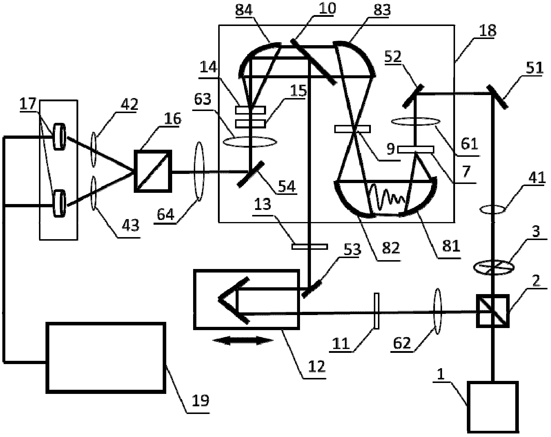
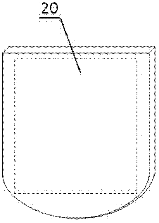
[0031] A waste oil detection system, such as figure 1 , figure 2 shown. Including: femtosecond laser 1, transflective beam splitter 2, optical chopper 3, reflector, focusing lens, gallium arsenide photoconductive antenna 7, parabolic mirror, sample box 9, high resistance silicon reflector 10, An optical path delay device 12 , an electro-optic crystal 14 , a Walstone prism 16 , a photodetector 17 , and a lock-in amplifier 19 .

[0032]A) At the exit position of the femtosecond laser 1, a semi-reflective and semi-transparent beam splitter 2 is arranged to divide the pulsed laser light into a pumping light path and a detection light path; the optical chopper 3, the first attenuation plate 41, The first reflector 51, the second reflector 52 and the first focusing lens 61 are located on the pumping light path between the semi-reflective beam splitter 2...


PUM


Abstract

The invention provides a swill-cooked dirty oil detecting system. A semi-reflection and semi-transmission beam splitter is arranged at an emission port of a femtosecond laser; a pulse laser light is split into a pump light path and a detecting light path; the pump light path is connected with a photochopper, a first attenuation sheet, a first reflecting mirror, a second reflecting mirror, a first focusing lens and a gallium arsenide photoconductive antenna in sequence; a sample box is arranged on a confocal point of second and third paraboloidal mirrors; a second collimating lens, a half wave plate, a light path delay device, a third reflecting mirror, a polarizer and a high resistivity silicon reflecting mirror are arranged on the detecting light path in sequence; the femtosecond laser after being sampled by an electrooptic crystal is detected by being directed with a photoelectric detector via a quarter wave plate, a third focusing lens, a fourth reflecting mirror, a fourth focusing lens, a Wollstone prism as well as second and third attenuation sheets; and the variation of voltage magnitude caused by terahertz waves is recorded, so that a time domain terahertz signal including swill-cooked dirty oil information is obtained. The swill-cooked dirty oil detecting system provided by the invention has the advantages of simple detecting process, high efficiency, rapidness and accurate detecting result.

Description

technical field [0001] The invention belongs to the technical field of waste oil detection and identification, and in particular relates to a detection and identification system and method for judging waste oil similar to edible oil but of different quality. Background technique [0002] Waste oil is a non-edible oil with extremely poor quality and hygiene, and the peroxide value, acid value, moisture, carbonyl value, malondialdehyde, aflatoxin B1, etc. seriously exceed the standard. Waste oil mainly has three kinds of sources: the one, the greasy floating thing in the sewer or the leftovers of hotel, restaurant, leftovers (common name swill), the oil that obtains after simple processing and refining, the 2nd, inferior pork, pig viscera, pigskin processing And the oil produced after refining; the third is the oil that does not meet the regulations after repeated frying or adding new oil to the repeatedly used oil, so it is called deep frying oil. [0003] Compared with edib...

Claims


Application Information

Patent Timeline
IPC IPC(8): G01N21/35G01N21/3586
CPCG01N21/3586
Inventor 朱亦鸣杜少卿彭滟沈惠中陈麟徐公杰倪争技吴家荣彭宁嵩马兰凤
Owner UNIV OF SHANGHAI FOR SCI & TECH
Why Eureka
Eureka Blog
Learn More