
Titanium dioxide photo-catalytic micro-reactor

A micro-reactor, titanium dioxide technology, applied in the field of high-efficiency TiO2 photocatalytic micro-reactor, can solve the problems of low mass transfer efficiency, small effective catalytic area, difficult catalyst recovery, etc., and achieves convenient and simple operation and post-processing, online and The effect of convenient offline detection and easy repeated use for a long time

Inactive Publication Date: 2012-07-18
NORTHWEST UNIV
View PDF1 Cites 25 Cited by
  • Summary
  • Abstract
  • Description
  • Claims
  • Application Information

AI Technical Summary

Problems solved by technology

[0003] However, currently the TiO 2 The development of photocatalytic reactors is seriously lagging behind that of TiO 2 The research and development of photocatalysts restrict TiO 2 Practical applications in the field of photocatalysis
Conventional photoreactors based on TiO 2 The existence forms in the reaction system are divided into fixed type (such as liquid film reactor, fixed packed composite bed photocatalytic reactor, etc.) and suspension type (such as fluidized bed photocatalytic reactor, photocatalytic and membrane separation Chemical reactors, photocatalytic and magnetic separation reactors, etc.), although fixed reactors solve the problem of catalyst recovery and reuse, but have a small effective catalytic area, attenuation of light passing through the reaction solution, and low light utilization efficiency. High, low mass transfer efficiency and other issues
Although the suspension reactor improves the effective utilization area and catalytic effect of the catalyst through the suspension and dispersion of the catalyst, it has disadvantages such as difficult recovery of the catalyst, troublesome post-processing, poor reusability, or complicated equipment.

Method used


Image

  • Titanium dioxide photo-catalytic micro-reactor
  • Titanium dioxide photo-catalytic micro-reactor
  • Titanium dioxide photo-catalytic micro-reactor

Examples


Embodiment Construction

[0033] The specific implementation manners of the present invention will be described in further detail below in conjunction with the accompanying drawings.

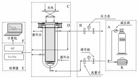
[0034] refer to figure 1 , taking the water circulation type as an example, the electric heating type is similar. Efficient TiO of the present invention 2 The photocatalytic microreactor and the photocatalytic degradation system of organic matter (such as 4-nitrophenol) in aqueous solution are mainly composed of gas supply system A, regulation system B, light source system C, reaction system D, detection system E and data processing system F , whose core is the reaction system D, where,

[0035] Gas supply system A includes gas cylinders (such as CO 2 , O 2 etc.) and pressure reducing valve. If the reaction only needs to blow in air, the air supply system only needs an air pump of appropriate power.

[0036] Regulating system B includes rotameters, barometers and gas regulating valves on the inlet and outlet pipeli...


PUM

PropertyMeasurementUnit
Diameteraaaaaaaaaa
Lengthaaaaaaaaaa

Abstract

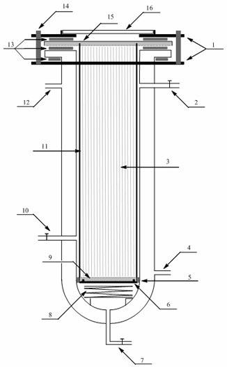
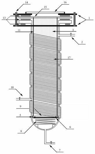
The invention discloses a titanium dioxide photo-catalytic micro-reactor, characterized in that in the reactor, the lower ends of fibers are supported on a porous glass sand separator through a porous glass sheet, the upper end is fixed with a translucent sheet, the bottom of the reactor is provided with an air inlet pipe, and the side of the reactor is provided with a testing port and an injection port. According to the invention, the ratio of effective catalytic surface area to reactive volume is raised, the incident mode of a light source is changed into an internal reflection mode from a traditional external reflection mode, thus the attenuation after the light passes through the solution is reduced, and the utilization rate of the light is raised; compared with TiO2 nano-particles, the TiO2 nanotubes used as the photoreaction catalyst have higher catalysis catalysis effect; and compared with traditional coating modes, the reaction layer obtained by the catalyst layer of the photoreaction unit is more uniform, compact and firm.

Description

technical field [0001] The invention relates to a high-efficiency TiO 2 A photocatalytic microreactor belongs to the technical field of chemical engineering equipment design. Background technique [0002] Since Fujishima and Honda discovered TiO in 1972 2 Since electrode photoinduced water splitting, TiO 2 The various unique properties exhibited make it favored in many research fields. TiO 2 The well-known advantages of photocatalytic activity, high stability, non-toxicity and easy acquisition make it the most potential photocatalytic material. In particular, in 1998, Kasuga first synthesized TiO by concentrated NaOH heat treatment. 2 Since nanotubes, like the nanotube revolution triggered by the discovery of carbon nanotubes by Iijima of NEC in 1991, the new effects brought by the new structure have excited many researchers. TiO 2 The research and application of nanotubes have made rapid progress in many fields, especially in the field of photocatalysis. [0003] Howe...

Claims


Application Information

Patent Timeline
IPC IPC(8): B01J19/12
Inventor 马晓迅王晨徐龙
Owner NORTHWEST UNIV
Learn More