Method for removing CO2 from blast furnace clean coal gas by using ionic liquid
A technology of ionic liquid and clean gas, which is applied in the direction of liquid washing gas purification, etc., to achieve the effects of strong solubility, easy desorption and regeneration, and avoiding secondary pollution
- Summary
- Abstract
- Description
- Claims
- Application Information
AI Technical Summary
Problems solved by technology
Method used
Image

Examples
Embodiment 1
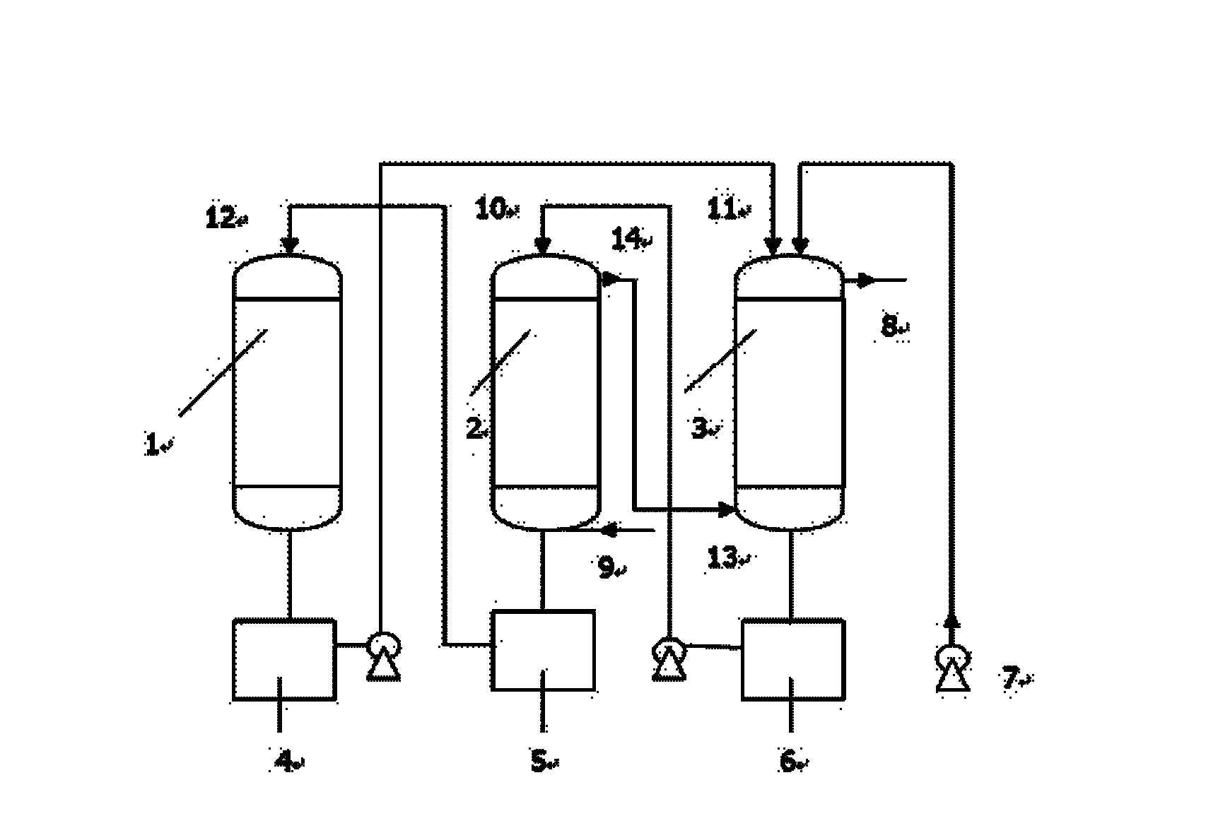
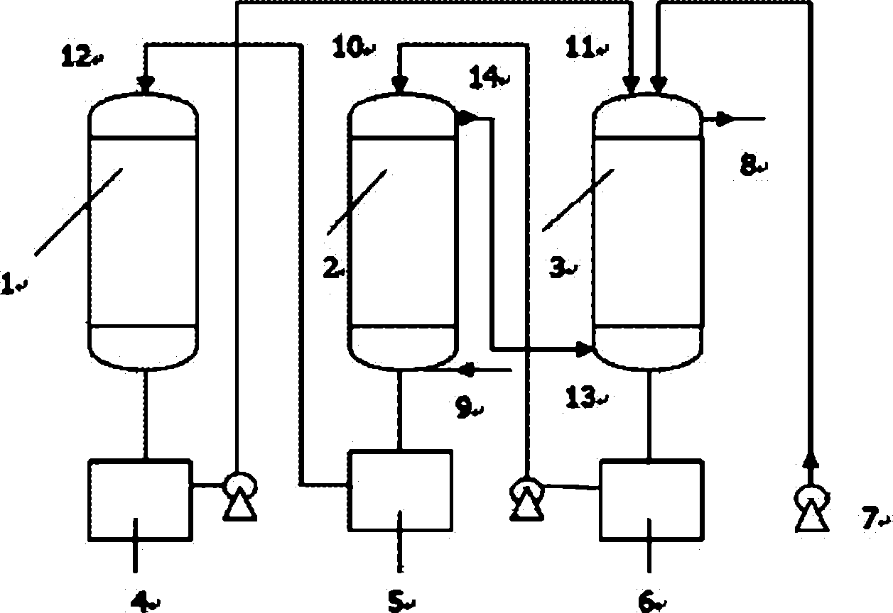
[0025] Removal of CO from blast furnace gas by using ionic liquid 2 method, such as figure 1 As shown, the blast furnace net gas flow path is as follows:
[0026] Clean blast furnace gas with a temperature between 20°C and 90°C after dedusting, CO 2 The gas content is 393g / m 3 , enter the tower from the air inlet 9 below the primary absorption tower 2, there is a gas distribution device in the tower, the pressure inside the tower is 0.01MPa ~ 0.03MPa, the blast furnace clean gas passes through the packing layer, and enters from the gas outlet 14 above the primary absorption tower 2 will be absorbed by CO 2 The final blast furnace clean gas is sent into the tower from the gas inlet 13 below the secondary absorption tower 3, and is absorbed again in the tower. There is a gas distribution device in the secondary absorption tower 3, and the blast furnace clean gas passes through the packing layer to remove CO 2 The final blast furnace clean gas is discharged from the gas outle...
Embodiment 2
[0030] The ionic liquid absorbent adopts imidazole amino acid ionic liquid N-methyl-N-n-butane imidazolium glycinate, the ratio of the amount of ionic liquid to the clean blast furnace gas substance is 18-2.6:1, and the primary absorption tower and the secondary absorption tower They all choose packed towers with Pall rings inside as fillers. The upper part of the two absorption towers is a liquid inlet pipe with a liquid distribution device, and the lower part is an air inlet with a gas distribution device. The desorption tower is a combined spray and plate tower. The other content of this embodiment is the same as that of Embodiment 1, and the CO of this embodiment 2 The removal rate is above 84.7%.
Embodiment 3
[0032]The ionic liquid absorbent uses ammonium salt amino acid ionic liquid tetramethylammonium lysine salt, the ratio of the amount of ionic liquid to the clean gas of the blast furnace is 20-3:1, and the primary absorption tower and the secondary absorption tower are both packed towers , with Pall rings inside as fillers. The upper part of the two absorption towers is a liquid inlet pipe with a liquid distribution device, and the lower part is an air inlet with a gas distribution device. The desorption tower is a spray tower. The other content of this embodiment is the same as that of Embodiment 1, and the CO of this embodiment 2 The removal rate is above 80.5%.
PUM
 Abstract
Description
Claims
Application Information
 - Generate Ideas
- Intellectual Property
- Life Sciences
- Materials
- Tech Scout
- Unparalleled Data Quality
- Higher Quality Content
- 60% Fewer Hallucinations
Browse by: Latest US Patents, China's latest patents, Technical Efficacy Thesaurus, Application Domain, Technology Topic, Popular Technical Reports.
© 2025 PatSnap. All rights reserved.Legal|Privacy policy|Modern Slavery Act Transparency Statement|Sitemap|About US| Contact US: help@patsnap.com