
Distillation separation method for oily wastewater

A technology for distillation separation and waste water, which is applied in the fields of energy waste water treatment, chemical instruments and methods, heating water/sewage treatment, etc. It can solve the important indicators of the repetition rate of industrial water, does not meet the development trend of industrial waste water treatment, does not Find obvious shortcomings and other problems, and achieve excellent environmental protection treatment capabilities, reduce the spread of odors, and achieve a wider range of pH values

Inactive Publication Date: 2012-08-22
SHENZHEN FRANCOOL TECH
View PDF0 Cites 7 Cited by
  • Summary
  • Abstract
  • Description
  • Claims
  • Application Information

AI Technical Summary

Problems solved by technology

[0005] Disadvantages: This technology is temporarily in the leading position in the world, and no obvious disadvantages have been found yet
[0006] Disadvantage: If solar and wind energy can be used for distillation, it will be more green and environmentally friendly
[0008] The random discharge of traditional 1T industrial wastewater will generate at least 2,000 yuan in environmental protection costs. For example, oily wastewater needs about 2,000-2,500 yuan / ton, or surface treatment needs 3,000-3,500 yuan / ton, and electroplating factories and other highly polluted liquids containing heavy metals It needs 3,500-4,000 yuan / ton, resulting in the cost of recovering 2,500 tons of oily liquid per year to exceed 5 million yuan. The cost is so expensive that it does not conform to the development trend of industrial wastewater treatment and cannot meet the important indicators of industrial water repetition rate.

Method used


Image

  • Distillation separation method for oily wastewater
  • Distillation separation method for oily wastewater
  • Distillation separation method for oily wastewater

Examples


Embodiment Construction

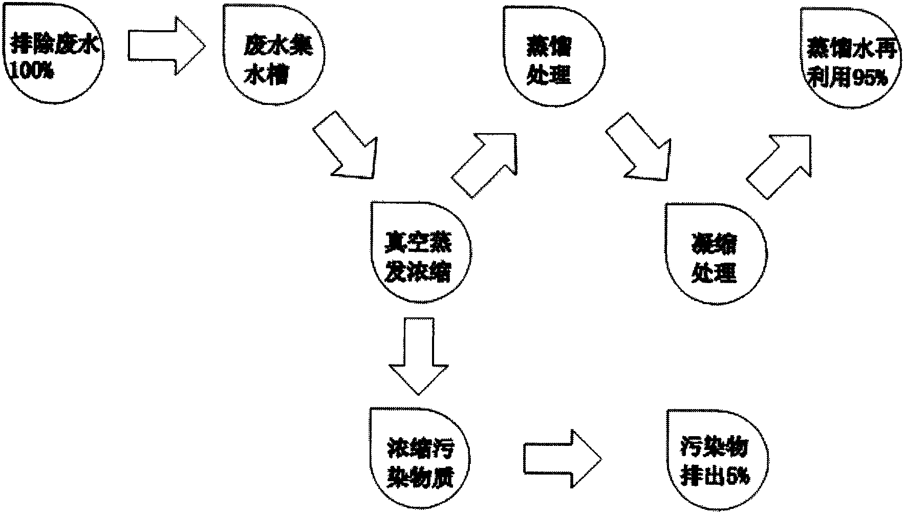
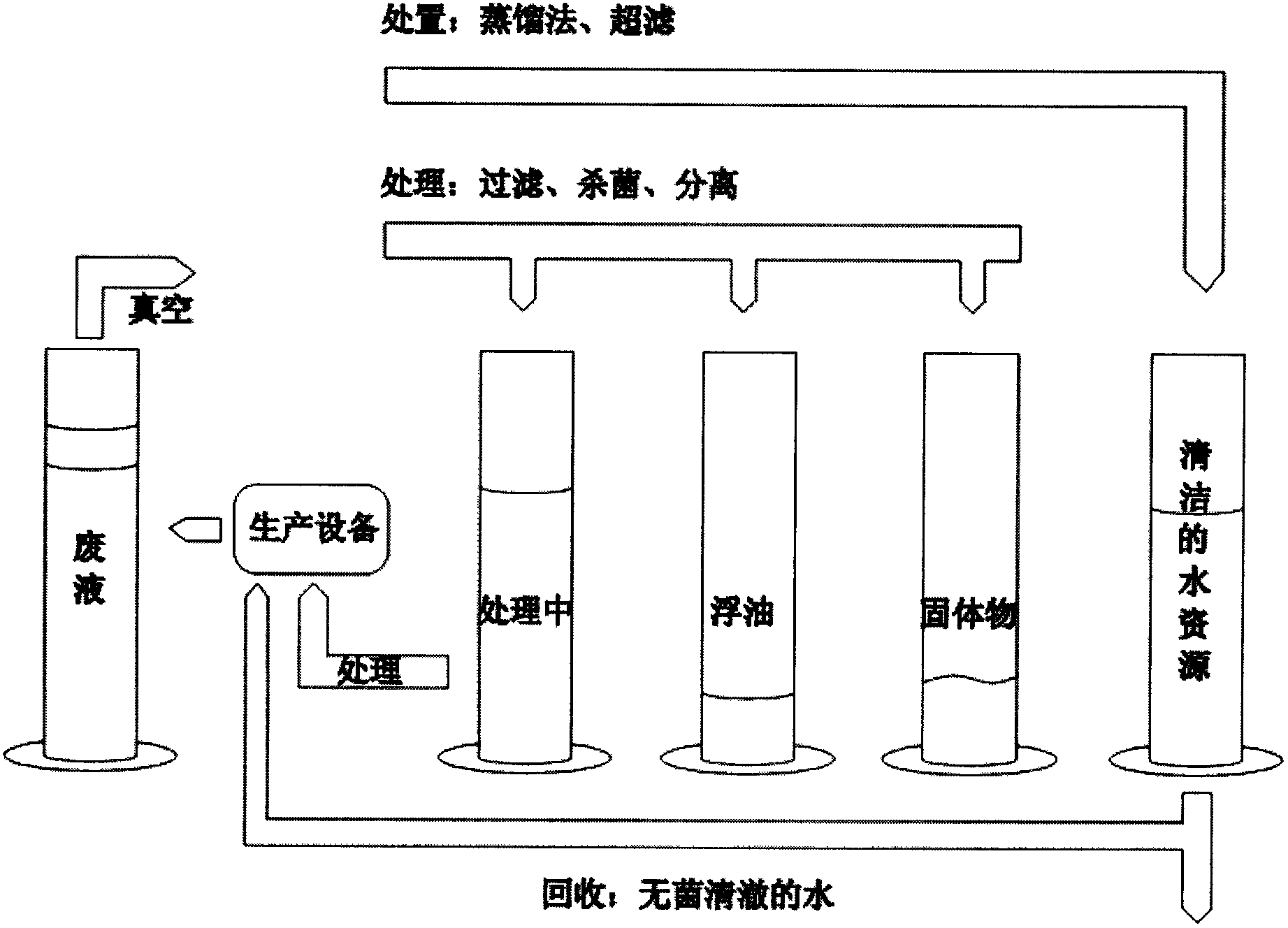
[0027] Such as figure 1 , figure 2 As shown, the steps include:

[0028] 1) Vacuum evaporation is used for vacuum evaporation of industrial wastewater, and the water in the wastewater is gasified into gas.

[0029] 2), distillation treatment, condensation treatment, the way of said distillation treatment is distillation method, the gas liquefaction by vacuum evaporation carries out distillation and condenses into distilled water, carries out ultrafiltration through ultra-strong filter, distills 90%-95% The water is condensed and discharged, while reducing waste by nearly 95%, while killing bacteria, reducing the spread of odors, and reentering clean water resources for industrial recycling.

[0030] 3) Concentrate the pollutants, concentrate 5%-10% of the waste, filter the waste to separate each waste gas, and finally discharge the waste to achieve the effect of zero emission.

[0031] 4) Pollutants are discharged, and the concentrated pollutants are discharged.

[0032] ...


PUM


Abstract

The invention discloses a distillation separation method for oily wastewater, which comprises the steps of vacuum evaporation, distillation treatment and condensation treatment, and pollutant concentration and pollutant discharge, wherein the vacuum evaporation is used for evaporating industrial wastewater in vacuum, and moisture in the wastewater is gasified into gas; the distillation treatment and the condensation treatment are used for distillating and separating the evaporated gas after being liquefied, and the separated water is distillated to obtain 90-95% of water through concentration and then is industrially recycled; the pollutants left after wastewater evaporation are concentrated so as to concentrate out 5-10% of waste; and the concentrated pollutants are discharged. Breakthrough zero liquid discharge and zero pollution are realized; and the treatment cost is reduced, and a clean water treatment process is used for producing clean water. According to the method disclosed by the invention, sewage discharge and recording in government departments are not needed, evaporation and concentration are carried out at a low temperature in a vacuum state, and the environmental design is safe, so that 24-hour fully automatic operation and an automatic cleaning function are realized.

Description

technical field [0001] The invention relates to the field of environmental protection treatment of industrial wastewater, in particular to a method for distillation and separation of industrial oily wastewater. Background technique [0002] The repetition rate of industrial water use is an important index for the construction of ecological cities in my country, and it is also a "green index" to measure the performance of local officials. It has been included in the mandatory industrial wastewater treatment standards in many economically developed areas; Under the increasingly urgent situation, the development trend of industrial wastewater treatment is to recycle water and pollutants as useful resources and implement closed loop. This can be divided into integrated recycling of water and pollutants, and separate recycling of water and pollutants. [0003] Structure: filtration system, heating distillation system, control system, cooling separation system, collection and disc...

Claims


Application Information

Patent Timeline
Patent Type & Authority Applications(China)
IPC IPC(8): C02F1/04C02F9/10
CPCY02W10/33Y02W10/37
Inventor 范文智何波
Owner SHENZHEN FRANCOOL TECH
Learn More