Method for repairing roller sleeve of continuous casting roller

A repair method and continuous casting roll technology, which is applied in the direction of welding media, laser welding equipment, welding/cutting media/materials, etc., can solve problems such as increased production costs, reduced precision of casting machines, and damage to roll sleeves, so as to reduce maintenance costs , Improve production efficiency, improve the effect of service life

Inactive Publication Date: 2012-10-17
YANSHAN UNIV
View PDF6 Cites 23 Cited by
  • Summary
  • Abstract
  • Description
  • Claims
  • Application Information

AI Technical Summary

Problems solved by technology

Continuous casting roll sleeves are generally made of 35CrMo or 42CrMo material through forging billet, quenching and tempering heat treatment and finishing. However, because the outer surface of the roll sleeve is directly in contact with the high-temperature billet, the temperature of the high-temperature billet is between 900 and 1100 °C. The temperature of the outer surface of the roller sleeve reaches 600-700°C, which is very easy to produce oxidation, and the cooling water spray will cause serious water vapor corrosion. The outer surface of the roller sleeve is subjected to repeated heating and cooling without interruption, and thermal fatigue cracks will occur destroy
Due to the harsh conditions of high temperature, water, and steam in actual production, cracks often occur on the surface of the roller sleeve, and then develop into annular cracks, resulting in fracture and failure of the roller sleeve, which directly affects the service life of the roller sleeve.
In addition, if the wear and bending of the continuous casting roll sleeve is serious, it will lead to a decrease in the accuracy of the casting machine, which will cause serious quality problems in the produced billet
Therefore, the roller sleeve is often damaged, which not only increases the direct production cost, but more importantly, directl

Method used


Image

  • Method for repairing roller sleeve of continuous casting roller
  • Method for repairing roller sleeve of continuous casting roller

Examples


Embodiment 1

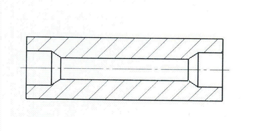
[0024] Example 1 Taking the continuous casting roll sleeve repaired with a material of 35CrMo and a size of φ230mm×618mm as an example, firstly, a preliminary inspection is performed on the roll sleeve whose material is 35CrMo to be repaired; figure 1 As shown, measure the size of each part of the roller sleeve to check whether it is suitable for the laser cladding repair standard, and then use the turning method to remove the 3mm fatigue layer on the surface of the roller sleeve, and conduct magnetic particle inspection and ultrasonic flaw detection to ensure that the surface of the roller sleeve and the base material are free of serious cracks. For defects, the outer diameter of the roller sleeve is processed to φ224mm; the proportionally prepared Ni45 and WC powders are put into a mechanical powder mixer and fully mixed by a mechanical mixing method. The mixing time is 1.5 hours, and the mixing ratio of the alloy powder is : Ni45 powder accounts for 75% of the total mass, a...

Embodiment 2

[0025] Example 2 Taking the repair of the continuous casting roll sleeve made of 42CrMo and with a size of φ230mm×618mm as an example, first, a preliminary inspection is carried out on the roll sleeve made of 42CrMo material to be repaired; the dimensions of each part of the roll sleeve are measured to see if it is suitable for laser melting. Then use the turning method to remove the 3mm fatigue layer on the surface of the roller sleeve, conduct magnetic particle inspection and ultrasonic flaw detection to ensure that there are no serious defects such as cracks on the surface of the roller sleeve and the base material, and process the outer diameter of the roller sleeve to φ224mm; use mechanical mixing Methods The Ni45 and WC powders prepared in proportion were put into a mechanical powder mixer and mixed fully. The mixing time was 1.5 hours. The mixing ratio of the alloy powder was: Ni45 powder accounted for 80% of the total mass, and WC powder accounted for 80% of the total ma...

Embodiment 3

[0026] Example 3 Taking the repair of a continuous casting roll sleeve made of 42CrMo and with a size of φ150mm×600mm as an example, a preliminary inspection is performed on the roll sleeve made of 42CrMo to be repaired; Then use the turning method to remove the 2mm fatigue layer on the surface of the roller sleeve, conduct magnetic particle inspection and ultrasonic flaw detection to ensure that there are no serious defects such as cracks on the surface of the roller sleeve and the base material, and process the outer diameter of the roller sleeve to φ146mm; use mechanical mixing Methods Put the Ni45 and WC powder prepared in proportion into a mechanical powder mixer and mix them thoroughly. The mixing time is 2 hours. The mixing ratio of the alloy powder is: Ni45 powder accounts for 80% of the total mass, and WC powder accounts for 80% of the total mass. 20%, preheat the 42CrMo roller sleeve to be clad to 350°C, adopt the coaxial powder feeding method, the powder transmission...


PUM

PropertyMeasurementUnit
Thicknessaaaaaaaaaa
Granularityaaaaaaaaaa

Abstract

The invention discloses a method for repairing a roller sleeve of a continuous casting roller. The method comprises the following steps of: preliminarily checking the roller sleeve; measuring the size of each part of the roller sleeve, removing a fatigue layer on the surface of the roller sleeve, and performing magnetic particle inspection and ultrasonic flaw detection; preparing Ni45 and WC alloy powder by adopting a mechanical mixing method, preheating the roller sleeve, coating the alloy powder on the surface of the roller sleeve by adopting a coaxial powder feeding method and scanning with a high-power CO2 laser device, thermally treating the whole roller sleeve, and slowly cooling together with a furnace; and performing rough machining and precision machining on the roller sleeve of the continuous casting roller meeting the requirements by using a lathe. Compared with the prior art, the method has the advantages that the service life of the roller sleeve is prolonged; consumption is reduced; the roller sleeve is high in abrasion resistance and heat resistance; and the method is simple, strong in controllability and low in cost, and saves the alloy material.

Description

technical field [0001] The invention relates to a method for repairing mechanical parts, in particular to a method for repairing continuous casting roll sleeves. Background technique [0002] The continuous casting machine is an important steel casting equipment in the field of metallurgy. The roller sleeve used on the continuous casting machine is one of the most important parts in the continuous casting machine, and it is used in the crystallizer and the support and guide section. Its excellent performance Inferiority and service life will directly affect the continuous casting machine's operating rate, equipment accuracy, billet quality and maintenance cost. Continuous casting roll sleeves are generally made of 35CrMo or 42CrMo material through forging billet, quenching and tempering heat treatment and finishing. However, because the outer surface of the roll sleeve is directly in contact with the high-temperature billet, the temperature of the high-temperature billet is ...

Claims


Application Information

Patent Timeline
IPC IPC(8): B23P6/04B23K26/34B23K26/42B23K35/30B23K26/342B23K26/60
Inventor 付宇明郑丽娟张金森王军刘会莹
Owner YANSHAN UNIV
Why Eureka
Try Eureka