Method for preparing low-temperature interconnection/high-temperature serving joints by using nano intermetallic compound particles

A nano-metal, high-temperature service technology, applied in the field of micro-connection, can solve the problems of restricting wide application, high cost, affecting electrical and thermal conductivity, etc., and achieve the effect of good compatibility and low cost

Active Publication Date: 2013-02-13
HARBIN INST OF TECH
View PDF6 Cites 29 Cited by
  • Summary
  • Abstract
  • Description
  • Claims
  • Application Information

AI Technical Summary

Problems solved by technology

According to the thermodynamic properties of nanoparticles, the melting point of silver nanoparticles can be reduced to below 100°C, and the connection can be realized at 150°C, and the service temperature of its joints can reach above 300°C, that is, low-temperature connection and high-temperature service are realized; however, the connection process It takes a long time (generally, when the connection temperature is 150°C, the connection time needs to be more than 30 minutes to form a stable connection), the joint is porous structure (the porosity is about 15%, which affects the electrical and thermal conductivity), and the cost is high, which restricts the connection. Wide application of materials
All intermetallic compound interconnection is to fully react the interface at normal brazing temperature until the joint is completely transformed into an intermetallic compound. The service temperature that the joint can withstand is determined by the intermetallic compound with a higher melting point rather than the solder. It can also be used Realize low-temperature connection and high-temperature service, but the reaction time needs at least tens of minutes, the production efficiency is too low, and the components of the joint cannot be precisely controlled, so it is difficult to achieve large-scale industrial application

Method used


Image

  • Method for preparing low-temperature interconnection/high-temperature serving joints by using nano intermetallic compound particles

Examples


Embodiment 1

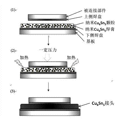
[0016] Such as figure 1 As shown, nano-Cu 6 sn 5 The method for forming a solder paste interconnection joint includes the following steps:

[0017] Step 1: Prepare Cu with a diameter of about 50nm 6 Su 5 particles;

[0018] Step 2: Mix the above nanoparticles with dispersant fish oil, binder α-terpineol, thinner alcohol, and flux in an appropriate amount, and the mixing mass ratio is 80:5:6:4:5;

[0019] Step 3: Use 150W ultrasonic vibration for 60min to make nano-Cu 6 sn 5 The particles are uniformly dispersed in the organic solvent formulated in step 2 to make nano-Cu 6 sn 5 solder paste;

[0020] Step 4: the above nano-Cu 6 sn 5 Put the solder paste on the substrate, complete the alignment of the pads of the parts to be soldered and the pads of the substrate, and apply a pressure of 5MPa;

[0021] Step 5: Put the above system into the reflow furnace, and continue to perform the following actions: heat at a speed of 2~4°C / s to 120~150°C to complete the preheating...

Embodiment 2

[0024] Nano-Cu 3 The method for forming a Sn solder paste interconnection joint includes the following steps:

[0025] Step 1: Prepare Cu with a diameter of about 60nm 3 Sn particles;

[0026] Step 2: Mix the above nanoparticles with dispersant polyvinyl acetate, binder α-terpineol, diluent terpineol, and rosin in an appropriate amount, and the mixing ratio is 82:5:4:4:5;

[0027] Step 3: use 150W ultrasonic vibration for 50min to make nano-Cu 3 Sn particles are uniformly dispersed in the organic solvent formulated in step 2 to make nano-Cu 3 Sn solder paste;

[0028] Step 4: Use the dispensing method to apply the above nano-Cu 3 Place the Sn solder paste on the substrate, complete the alignment of the pads of the parts to be soldered and the pads of the substrate, and apply a pressure of 10MPa;

[0029] Step 5: Put the above system into the reflow furnace, and continue to perform the following actions: heat up to 150°C at a rate of 2~4°C / s to complete the preheating sta...

Embodiment 3

[0031] Nano Ag 3 The method for forming a Sn solder paste interconnection joint includes the following steps:

[0032] Step 1: Prepare Ag with a diameter of about 70nm 3 Sn particles;

[0033] Step 2: Mix the above nanoparticles with dispersant polyethylene glycol ester, binder α-terpineol, diluent ethanol, and rosin in an appropriate amount, and the mixing ratio is 82:5:4:4:5;

[0034] Step 3: use 160W ultrasonic vibration for 45min to make nano Ag 3 Sn particles are uniformly dispersed in the organic solvent formulated in step 2 to make nano Ag 3 Sn solder paste;

[0035] Step 4: The above nano-Ag is printed by screen printing method 3 Place the Sn solder paste on the substrate, complete the alignment of the pads of the parts to be soldered and the pads of the substrate, and apply a pressure of 10MPa;

[0036]Step 5: Put the above system into the reflow furnace, and continue to perform the following actions: heat up to 150°C at a rate of 3°C / s to complete the preheatin...


PUM

PropertyMeasurementUnit
diameteraaaaaaaaaa
melting pointaaaaaaaaaa
diameteraaaaaaaaaa

Abstract

The invention discloses a method for preparing low-temperature interconnection / high-temperature serving joints by using nano intermetallic compound particles, which relates to a packaging and assembling interconnected method for electronic devices. The method specifically comprises the following steps: 1, placing nano intermetallic compound soldering paste on a substrate, completing a process of aligning a component to be welded, and exerting a pressure; and 2, placing the system into a reflow oven, and through the stages of preheating, heat preservation, reflowing and cooling, completing the volatilization of organic matters, the uniform sintering of nano intermetallic compound particles and the wetting and interface reaction of a pad. Because nano intermetallic compound particles are applied to the method disclosed by the invention, the great surface activity of the nano particles can provides a powerful driving force for the sintering process thereof, so that the low-temperature connection compatible with the traditional reflow soldering process and far lower than the melting point of a block thereof is realized, and then a joint with good performances is formed, therefore, the low-temperature bonding / high-temperature serving is realized on the premise of low cost, good compatibility with the traditional process, and high production efficiency.

Description

technical field [0001] The invention belongs to the technical field of micro-connection, and relates to a packaging, assembly and interconnection method for electronic devices, in particular to a method for preparing low-temperature interconnection and high-temperature service joints by using nanometer intermetallic compound particles. Background technique [0002] Connection technology is one of the core technologies in electronic device packaging, LED packaging, microsystem packaging, and power component packaging. According to Moore's Law, the power of packaged components continues to rise and the pin density continues to increase, making it necessary to serve at higher and higher temperatures and ensure long-term reliability. However, traditional solder alloys or conductive silver pastes cannot work reliably in high-temperature environments, and the relatively poor high-temperature service performance of interconnection parts has become one of the main bottlenecks restri...

Claims


Application Information

Patent Timeline
Patent Type & Authority Applications(China)
IPC IPC(8): B23K1/008B23K1/20B23K35/24B23K35/363
CPCH01L24/29H01L24/83H01L2224/32503H01L2224/32507H01L2224/8381H01L2224/8384H01L2224/293H01L2224/29294H01L2924/203H01L2224/83815H01L2924/0002
Inventor 王春青钟颖杭春进
Owner HARBIN INST OF TECH
Why Eureka
Try Eureka