Hydration absorption gas stripping device and method for recycling ethylene and ethane from catalytic cracking dry gas or ethylene cracking gas

A technology of hydration absorption and catalytic cracking, which is applied in chemical instruments and methods, ethylene production, hydrocarbons, etc., to achieve the effects of reduced process energy consumption, reduced investment costs, and reduced operating costs

Inactive Publication Date: 2014-05-07
TIANJIN UNIV
View PDF3 Cites 2 Cited by
  • Summary
  • Abstract
  • Description
  • Claims
  • Application Information

AI Technical Summary

Problems solved by technology

The gas phase outlet at the top of the hydrate decomposer

Method used


Image

  • Hydration absorption gas stripping device and method for recycling ethylene and ethane from catalytic cracking dry gas or ethylene cracking gas
  • Hydration absorption gas stripping device and method for recycling ethylene and ethane from catalytic cracking dry gas or ethylene cracking gas
  • Hydration absorption gas stripping device and method for recycling ethylene and ethane from catalytic cracking dry gas or ethylene cracking gas

Examples


Embodiment 1

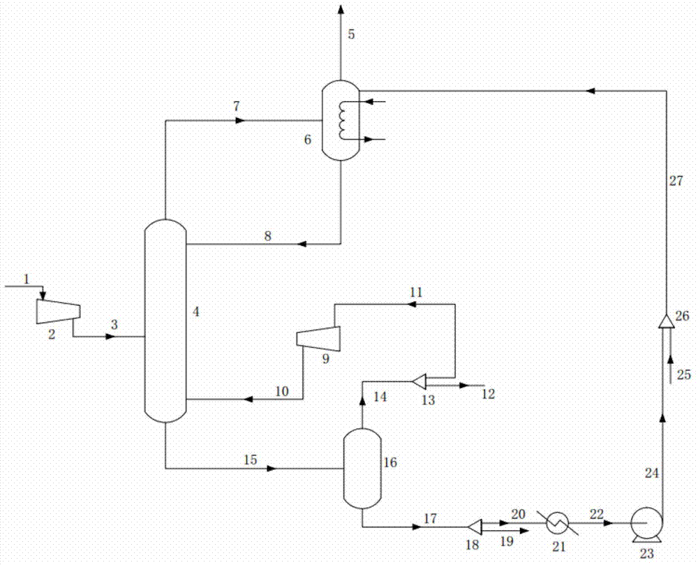
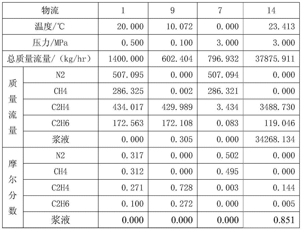
[0027] The molar composition of raw material gas 1 is 31.7%N2+32.1%CH4+27.1%C2H4+10.0%C2H6, the mass flow rate is 1400kg / hr, and the temperature is 20°C. Diesel oil and water are used as slurry in the process, and the mass flow rate of the total circulating slurry 27 is 37875.911kg / hr. Under standard conditions, the gas-liquid ratio in the hydration reactor 6 is 100:1.

[0028] The compressor 2 compresses the feed gas 1 to 3Mpa, the hydration absorption tower 4 operates at 3Mpa, the total balance stage is 15, and the compressed feed gas is fed in the 8th stage. The hydrate decomposer 16 is adiabatically flashed at 0.1Mpa to decompose. The heat exchanger 21 cools the internal circulating slurry 20 to 0°C, and the hydrate reactor 6 operates at 0°C and 3Mpa. The stripping compressor compresses the reflux to 3Mpa and enters from the bottom of the hydration absorption tower 4 . The results of the separation are shown in Table 1. Table 1 shows that the mole fraction of C2+ in th...

Embodiment 2

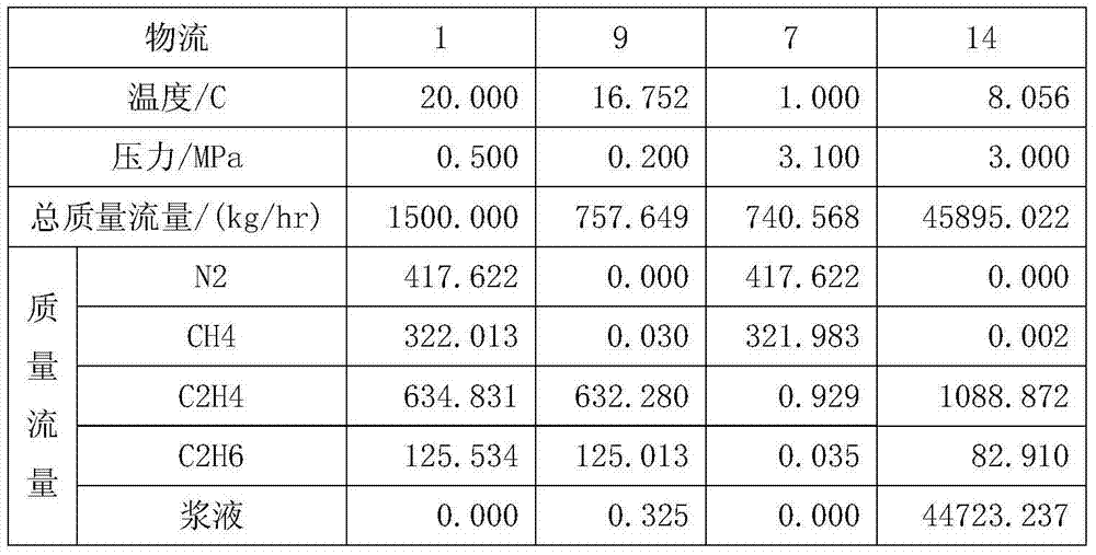
[0032] The molar composition of raw material gas 1 is 24.1%N2+32.5%CH4+36.6%C2H4+6.8%C2H6, the mass flow rate is 1500kg / hr, and the temperature is 20°C. Diesel oil and water are used as slurry in the process, and the mass flow rate of the total circulating slurry 27 is 45895.022kg / hr.

[0033] The compressor 2 compresses the feed gas 1 to 3.1Mpa, the hydration absorption tower 4 operates at 3.1Mpa, the total balance stage is 12, and the compressed feed gas is fed in the sixth stage. The hydrate decomposer 16 is adiabatically flashed at 0.2Mpa to decompose. The heat exchanger 21 cools the internal circulating slurry 20 to 1°C, and the hydrate reactor 6 operates at 1°C and 3.1Mpa. The stripping compressor compresses the reflux to 3.1Mpa and enters from the bottom of the hydration absorption tower 4 . The separation results are shown in Table 2. Table 2 shows that the mole fraction of C2+ in the product gas 12 is above 99.9%, and the recovery rate is above 99.5%, realizing the...


PUM


Abstract

The invention provides a hydration absorption gas stripping device and method of for recycling ethylene and ethane from catalytic cracking dry gas or ethylene cracking gas. The catalytic dry gas or ethylene cracking gas firstly enters a hydration absorption tower and is concentrated with slurry in the slurry, most of C2 components enter a tower bottom through the absorption effect, and the lean gas is discharged from a tower top and enters a hydration reactor. All C2 components in the hydration reactor enter the slurry in a form of hydrate, and the waste is directly discharged. The absorption slurry at the tower bottom of the hydration absorption tower is dissolved in a hydrate dissolving device, and the slurry is recycled after cooling and pressurization. By combining the absorption effect with a hydration separation process and using the concentration effect of the absorption process, the hydration separation process has the advantage of high separation efficiency for low-concentration gases, and the obtained C2 product with concentration of 99.6% can directly enter an ethylene tower. The method provided by the invention is expected to replace the common cryogenic separation process.

Description

technical field [0001] The invention relates to a separation process of catalytic cracking dry gas and ethylene cracking gas, in particular to equipment and a method for recovering ethylene and ethane through the processes of hydration, absorption and gas stripping, belonging to the chemical technology. Background technique [0002] As a pillar industry of the petrochemical industry, the ethylene industry has always played an important role in the national economy. With the rapid development of my country's economy, the demand for ethylene output is getting higher and higher, and the existing ethylene plants can no longer meet the market demand. [0003] At present, polymer-grade ethylene is mainly obtained through cryogenic separation of pyrolysis gas, which mainly includes hydrogen, methane, ethylene, ethane and other heavier components. Cryogenic separation is based on the principle that different substances have different boiling points. At the same time, since the boi...

Claims


Application Information

Patent Timeline
IPC IPC(8): C07C11/04C07C9/06C07C7/00C07C7/11
CPCY02P30/40
Inventor 李鑫钢王珏辛峰李永红陈超李优史荣会陈英楠
Owner TIANJIN UNIV
Why Eureka
Try Eureka