Cr/CrN/(Ti, Al, Si, Cr)N composite hard coating and preparation method thereof

A kind of hard coating and coating technology, applied in coating, metal material coating process, ion implantation plating and other directions, can solve the problem that it is difficult to meet the user's requirements for the service life of tool coating, the combination of coating and tool The problems of poor force and non-nanocrystalline structure of the structure can achieve the effect of good diffusivity, uniform coating structure and good wear resistance.

Inactive Publication Date: 2014-05-14
SICHUAN UNIV
View PDF4 Cites 29 Cited by
  • Summary
  • Abstract
  • Description
  • Claims
  • Application Information

AI Technical Summary

Problems solved by technology

However, with the emergence and development of high-speed cutting and dry cutting, the usual TiN and TiAlN coatings have been difficult to meet the user's requirements for tool coating life
[0003] In order to improve the service life of tool coatings, the new TiAlSiN coatings and TiAlCrN coatings developed in recent years have been successively applied to the field of cutting tools, among which the structure of TiAlSiN coatings (Hao Du, Haibo Zhao, Ji Xiong, et al .Int.Journal of Refractory Metals and Hard Materials37(2013)60-66.) is amorphous Si 3 N 4 The structure is wrapped around the nano-TiAlN grains, so the coating can obtain very high hardness (46Gpa) and oxidation resistance, but as the hardness increases, the internal stress of the coating also increases accordingly, resulting in the bonding between the coating and the tool. Therefore, the most common failure mode of TiAlSiN coating in the cutting process is coating peeling failure
TiAlCrN coating (G.S.Fox-Rabinovich.Surface and Coatings Technology200(2005)1804-1813), although it has high lubricity and oxidation resistance, its structure is not nanocrystalline, and its hardness is low (30Gpa). prone to wear and tear in the process

Method used


Image

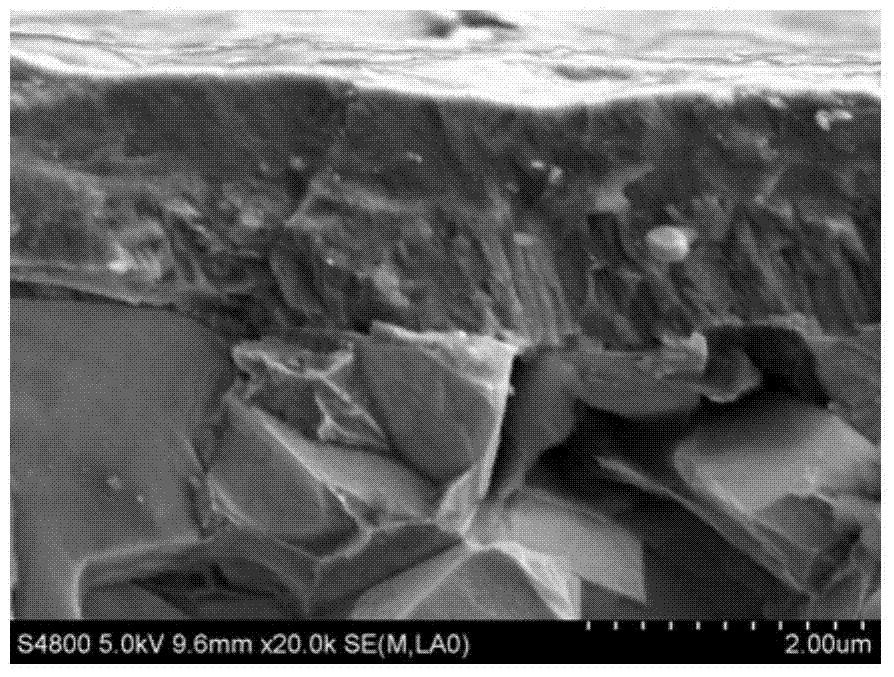
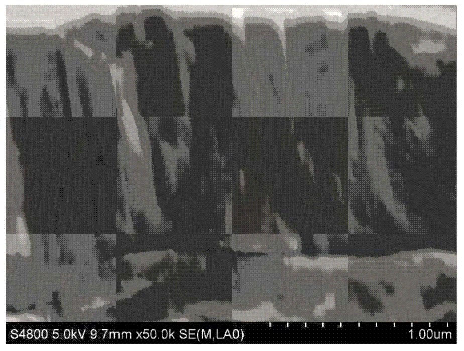
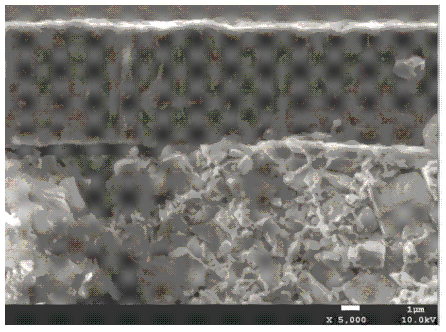
  • Cr/CrN/(Ti, Al, Si, Cr)N composite hard coating and preparation method thereof
  • Cr/CrN/(Ti, Al, Si, Cr)N composite hard coating and preparation method thereof
  • Cr/CrN/(Ti, Al, Si, Cr)N composite hard coating and preparation method thereof

Examples


Embodiment 1

[0034] 1) Put the cemented carbide taps after degreasing, sandblasting and ultrasonic cleaning by conventional methods into the coating chamber, and first vacuum the coating chamber to 5.0×10 -3 Pa, and then argon gas was introduced to make the total pressure in the coating chamber 3.0×10 -1 Pa, turn on the hot cathode ion column arc so that the current is 150A, and heat the tool for 150min;

[0035] 2) At a pressure of 1.8×10 -1 Under the protection of Pa argon gas, the DC bias voltage of the tool is controlled to -200V, the pulse bias voltage is -700V, and then the plasma generated by the hot cathode ion column arc with a current of 110A is used to bombard and clean the tool surface for 30 minutes;

[0036] 3) At a pressure of 8.0×10 -2 Under the protection of Pa argon gas, the Cr ingot is heated by a hot cathode ion column arc with a current of 200A to make it evaporate, and the tool is plated for 10 minutes to form a layer of Cr adhesion layer on the surface, and then th...

Embodiment 2

[0040] 1) Put the cemented carbide turning tool after degreasing, sandblasting and ultrasonic cleaning by conventional methods into the coating chamber, and first vacuum the coating chamber to 5.0×10 -3 Pa, and then argon gas was introduced to make the total pressure in the coating chamber 4.0×10 -1 Pa, turn on the hot cathode ion column arc to make the current 160A, and heat the tool for 100min;

[0041] 2) At a pressure of 1.5×10 -1 Under the protection of Pa argon gas, control the DC bias voltage of the tool to -150V, pulse bias voltage -600V, and then use the plasma generated by the hot cathode ion column arc with a current of 120A to bombard and clean the tool surface for 40min;

[0042] 3) At a pressure of 1.0×10 -1 Under the protection of Pa argon gas, the Cr ingot is heated by a hot cathode ion column arc with a current of 180A to evaporate it, and the tool is plated for 6 minutes to form a layer of Cr adhesion layer on the surface, and then the flow ratio of feeding...

Embodiment 3

[0046] 1) Put the cemented carbide drill bit after degreasing, sandblasting and ultrasonic cleaning by conventional methods into the coating chamber, and first vacuum the coating chamber to 5.0×10 -3 Pa, and then argon gas was introduced to make the total pressure in the coating chamber 3.0×10 -1 Pa, turn on the hot cathode ion column arc to make the current 140A, and heat the tool for 40min;

[0047] 2) At a pressure of 1.5×10 -1 Under the protection of Pa argon gas, control the DC bias voltage of the tool to -100V, and the pulse bias voltage to -500V, and then use the plasma generated by the hot cathode ion column arc with a current of 110A to bombard and clean the tool surface for 15 minutes;

[0048] 3) At a pressure of 1.2×10 -1 Under the protection of Pa argon gas, the Cr ingot is heated by a hot cathode ion column arc with a current of 210A to evaporate it, and the tool is plated for 7 minutes to form a layer of Cr adhesion layer on the surface, and then the flow rati...


PUM

PropertyMeasurementUnit
hardnessaaaaaaaaaa
thicknessaaaaaaaaaa
thicknessaaaaaaaaaa

Abstract

The invention discloses a preparation method of a Cr / CrN / (Ti, Al, Si, Cr)N composite hard coating. The preparation method comprises the steps of pretreatment, heating, plasma cleaning, Cr adhesion layer preparation, CrN transition layer preparation, (Ti, Al, Si, Cr)N anti-wearing layer preparation and the like. As a plasma enhanced intermediate frequency reaction magnetron sputtering technology is adopted in the preparation method provided by the invention, the ionization rate of a target material is substantially increased, so that the surface nano-hardness of the prepared composite hard coating can reach above 34 GPa, and the membrane base bonding force grade of the hard coating is HF1-HF2 of German Standard VDI3198. Therefore, the preparation method is suitable for preparation of the coating for high-speed dry-type cutting stainless steel, iron-based high-temperature alloy, high-strength constructional steel and anti-wearing cast steel cutters. The coating is simple in process and suitable for industrial production.

Description

technical field [0001] The invention belongs to the technical field of tool surface composite coating material and its preparation, and in particular relates to a Cr / CrN / (Ti, Al, Si, Cr)N composite hard coating and a preparation method thereof. The coating nano The hardness can reach more than 34Gpa, and the bonding strength of the film base is HF1~HF2 (German standard VDI3198). It is especially suitable as a surface coating for high-speed dry cutting stainless steel, iron-based superalloys, high-strength structural steel and wear-resistant cast steel tools. Background technique [0002] With the rapid development of industry, tools with coated surfaces are widely used in the field of material cutting. Studies have shown that the coating tool has the characteristics of high hardness, wear resistance and strong oxidation resistance, which can significantly improve the service life of the tool. However, with the emergence and development of high-speed cutting and dry cutting,...

Claims


Application Information

Patent Timeline
Patent Type & Authority Applications(China)
IPC IPC(8): C23C14/06C23C14/35C23C14/02
Inventor 赵海波杜昊王芳梁红樱鲜广
Owner SICHUAN UNIV
Why Eureka
Try Eureka