

Method for reducing welding hollows of LTCC substrate and metal base plate and LTCC substrate structure
A metal base plate and substrate technology, applied in the direction of electrical connection of printed components, printed circuit components, etc., can solve the problems of blocking organic substances and gas escape channels, reducing welding area and grounding area, affecting welding strength and grounding performance, etc. To achieve the effect of reducing the maximum void area, reducing the formation of voids, and reducing the void area
- Summary
- Abstract
- Description
- Claims
- Application Information
AI Technical Summary
Problems solved by technology
Method used
Image

Examples
Embodiment 1
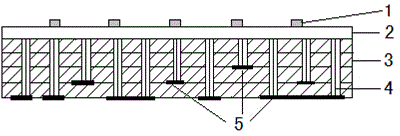
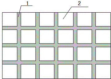
[0030] (1) Take 70wt% zinc borophosphate glass powder (composed of ZnO: 40wt%, B 2 o 3 : 10wt%, P 2 o 5 : 50wt%, softening point 410-440°C), add 30wt% mixture of ethyl cellulose and terpineol (in the mixture, ethyl cellulose accounts for 8wt%, terpineol accounts for 92wt%), through mixing and grinding Adjusted into the form of paste, the solder resist paste that can be used for printing is obtained. The solder resist paste is printed on the thick-film metallization layer on the surface of the LTCC substrate through a screen with grid lines prepared. The line width of the grid lines is 0.2 mm, and the line spacing is 3 mm. After the grid lines are heated at 130-150°C for 8-10 minutes and dried, they are put into a sintering furnace for sintering at a sintering temperature of 550°C. After sintering, the solder resist grid lines are firmly attached to the substrate metallization layer.
[0031] (2) Print the required low-temperature solder paste Sn62Pb36Ag2 on the surface o...
Embodiment 2
[0034] (1) Get 65wt% zinc borophosphate glass powder described in Example 1 and 8wt% inorganic additive Al 2 o 3 , grind it evenly, then add 27wt% of the mixture of ethyl cellulose and terpineol (in the mixture, ethyl cellulose accounts for 5wt%, terpineol accounts for 95wt%), and adjust it into a slurry form by mixing and grinding , which can be used for printing solder resist paste. The solder resist paste is screen-printed onto the thick film metallization layer on the surface of the LTCC substrate by making grid lines with a line width of 0.25mm and a line spacing of 2.5mm. After the grid lines are dried at 130-150°C for 8-10 minutes, they are put into a sintering furnace for sintering at a sintering temperature of 600°C. After sintering, the solder resist grid lines are firmly attached to the substrate metallization layer.
[0035] (2) Print the required medium-temperature solder paste Sn96.5Ag3.5 on the surface of the metallized layer of the substrate sintered with so...
Embodiment 3
[0038] Step (1) Get 65wt% zinc borophosphate glass powder described in example 1, add the mixture of 35wt% polyvinyl alcohol and butyl carbitol acetate (in the mixture, polyvinyl alcohol accounts for 4wt%, butyl carbitol acetate Alcohol acetate accounts for 96wt%), and other processes are the same as in Example 1.
[0039] X-ray inspection found that the welding void rate between the substrate and the metal base plate is about 17%, the largest void is less than 3% of the welding area, and the welding area is evenly distributed.
PUM
| Property | Measurement | Unit |
|---|---|---|
| Softening point | aaaaa | aaaaa |
| Width | aaaaa | aaaaa |
| Softening point | aaaaa | aaaaa |
Abstract
Description
Claims
Application Information