Large-area laser impact spot welding method and device based on nano-particle reinforcement

A nanoparticle and laser shock technology, applied in laser welding equipment, welding equipment, non-electric welding equipment, etc., can solve the problems of difficult application in industrial production, limited service life of welded parts, low tensile shear strength, etc., and achieve improvement. Mechanical properties, precise control of solder joint size, and the effect of increasing microhardness

Inactive Publication Date: 2014-12-24
JIANGSU UNIV
View PDF6 Cites 11 Cited by
  • Summary
  • Abstract
  • Description
  • Claims
  • Application Information

AI Technical Summary

Problems solved by technology

However, this welding process requires a certain impact angle, so the flight distance is extremely large, and the effect of air resistance under high-speed impact greatly affects the welding quality, and it is only suitable for single-point welding and is difficult to apply to industrial production
The paper "Laser shock welding of aluminum/aluminum and aluminum /copper plat

Method used


Image

  • Large-area laser impact spot welding method and device based on nano-particle reinforcement
  • Large-area laser impact spot welding method and device based on nano-particle reinforcement
  • Large-area laser impact spot welding method and device based on nano-particle reinforcement

Examples


specific Embodiment 1

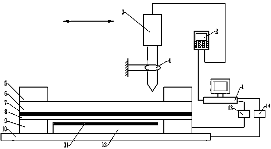
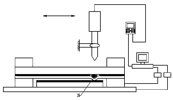
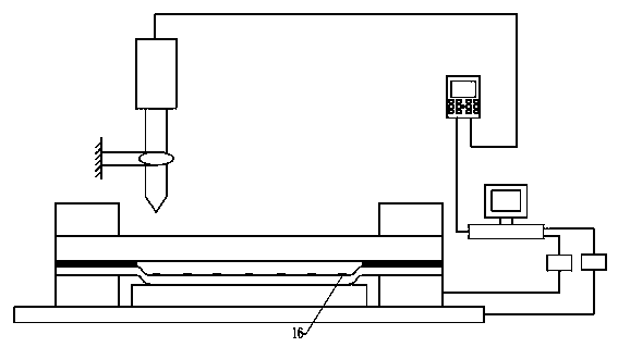
[0037] Specific embodiment 1: 2024 aluminum alloy with a thickness of 1 mm is selected for the workpiece, and T2 red copper with a thickness of 100 microns is selected for the flyer. First, polish the surface of the flyer and workpiece to be welded with 2000# metallographic sandpaper, and wash and dry it with alcohol. Use an inorganic binder (such as sodium silicate binder) to evenly coat silicon carbide particles with a particle size of 50 nm on the welding surface of the workpiece, and the thickness of the nanoparticle coating is 0.05 mm. Choose a transparent PC board coated with black paint with a thickness of 3 mm as the constraining layer, and use a cyanoacrylate adhesive to bond the flyer to the surface of the constraining layer coated with black paint. After the welding system composed of the workpiece, flyer and constrained layer is installed, adjust the three-coordinate moving platform to the preset welding station, use a strong pulse Nd:YAG laser to emit pulsed laser...

specific Embodiment 2

[0040] The difference between the second embodiment and the first embodiment is that the particle size of the nanoparticles is 10 nanometers, the thickness of the coating is 0.1 mm, the thickness of the flyer is 250 microns, the diameter of the laser spot is 7 mm, and the energy is 3 joules. This specific embodiment one is similar.

specific Embodiment 3

[0042] The difference between the third embodiment and the first embodiment is that the nanoparticles are titanium carbide, the particle size is 100 nanometers, the thickness of the coating is 0.5 mm, the thickness of the flyer is 500 microns, the diameter of the laser spot is 10 mm, and the energy is 50 μm. The welding effect is similar to that of the first embodiment.


PUM

PropertyMeasurementUnit
Thicknessaaaaaaaaaa
Thicknessaaaaaaaaaa
Thicknessaaaaaaaaaa

Abstract

The invention provides a large-area laser impact spot welding method and device based on nano-particle reinforcement and relates to the field of high-speed impact welding. The large-area laser impact spot welding method based on nano-particle reinforcement is characterized in that a high-energy short-pulse laser emits pulse laser light, a laser light beam forms a light spot through lens focusing to penetrate through a transparent PC board and irradiate a black paint layer, high-temperature and high-pressure plasmas are produced to inductively produce impact waves to drive a flyer to be locally bent and deformed and collide with a workpiece at high speed, micro-nano particles on the surface layer of the workpiece are directly implanted into a welding interface and thus spot cold welding of the flyer and the workpiece is realized. By implanting the micro-nano particles into the welding interface of the flyer and the workpiece during laser impact spot welding, heat affected zones and intermetallic compounds can be effectively prevented from being produced, the mechanical property of welding interface materials is obviously improved and the connecting strength of welded pieces is improved. In addition, the welding spot dimension can be accurately controlled, the device is simple and the method and the device are applicable to large-area spot welding of plates of different specifications.

Description

technical field [0001] The invention belongs to the field of high-speed impact welding. In particular, it is a welding technology using nanoparticle enhancement effect and laser-induced shock wave loading, specifically a large-area shock spot welding method and device suitable for flyer thickness in the micron-scale range. Background technique [0002] Spot welding is a high-speed and economical connection method, which is suitable for the manufacture of stamped and rolled thin plate components that can be overlapped, the joints do not require airtightness, and the thickness is less than 3mm. Commonly used spot welding techniques include resistance spot welding and laser spot welding. The principle is to rapidly heat the metal in contact with the central area to a highly plastic or molten state through resistance heat and laser irradiation, forming a lens-shaped liquid molten pool, and continue Maintain a certain pressure until the metal cools down to form a solder joint. ...

Claims


Application Information

Patent Timeline
IPC IPC(8): B23K20/06B23K26/22
CPCB23K26/22
Inventor 王霄顾宇轩徐艳如邱唐标马友娟张迪刘会霞
Owner JIANGSU UNIV
Why Eureka
Try Eureka