Non-linear Cerenkov radiation light source based on doped optical superlattice

An optical superlattice, nonlinear technology, applied in the field of lasers, can solve problems such as unreported, and achieve the effect of improving integration and wide application

Inactive Publication Date: 2014-12-24
NANJING UNIV
View PDF3 Cites 4 Cited by
  • Summary
  • Abstract
  • Description
  • Claims
  • Application Information

AI Technical Summary

Problems solved by technology

This form of radiation integrates the laser gain medium and the domain boundaries that generate nonlinear Cerenkov on a single crystal, which greatly improves the integration of the system. Related research has not been reported so far.

Method used


Image

  • Non-linear Cerenkov radiation light source based on doped optical superlattice
  • Non-linear Cerenkov radiation light source based on doped optical superlattice

Examples


Embodiment 1

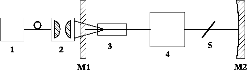
[0023] Such as figure 1 As shown, a nonlinear Cerenkov radiation source based on doped optical superlattice, including: laser pump source 1, input plane mirror M1, doped optical superlattice crystal 3, Q switch 4, polarizing lens 5 flat concave mirror M2. The input plane mirror M1 and the plano-concave mirror M2 together with the housing form an optical resonant cavity. The optical resonant cavity is a two-mirror cavity composed of a plane mirror and a flat-concave mirror. The coating of the input plane mirror M1 is highly transparent to the pump light and highly reflective to the fundamental wave light, and the coating of the plano-concave mirror M2 is highly reflective to the fundamental wave light. Doped optical superlattice crystal 3, Q switch 4 and polarizing lens 5 are located in the optical resonant cavity. Wherein, the Q switch 4 is located between the doped optical superlattice crystal 3 and the polarizing lens 5; the optical superlattice crystal 3 is located betwe...

Embodiment 2

[0027] In the structure of the foregoing embodiment 1, the laser pumping source 1 is a laser diode with an operating wavelength of 980 nm. The doped optical superlattice crystal 3 is lithium niobate or lithium tantalate optical superlattice crystal doped with 1% mole fraction of ytterbium (Yb). The wavelength of light emitted by ytterbium (Yb) ions is about 1060nm (different matrix materials correspond to slightly different laser emission wavelengths), that is, the fundamental wavelength of light is about 1060nm. The doped optical superlattice crystal 3 is placed in a direction in which the direction of the domain wall is parallel to the direction of the optical axis of the optical resonant cavity. The length of the light transmission direction of the doped optical superlattice crystal 3 is 1mm, and the two end faces are coated with a high-transmittance film for the fundamental wave light of 1060nm and the pump light of 980nm. The film system on the input plane mirror M1 is h...

Embodiment 3

[0029] In the structure of the foregoing embodiment 1, the laser pump source 1 is a laser diode with an operating wavelength of 808nm, and the doped optical superlattice crystal 3 is lithium tantalate or lithium niobate doped with 1% neodymium (Nd) in molar fraction Optical superlattice crystal (can also be doped with 2% mole fraction of MgO at the same time to enhance the anti-light damage threshold of the crystal at room temperature). The wavelength of light emitted by neodymium (Nd) ions is about 1083nm (different matrix materials correspond to slightly different laser emission wavelengths), that is, the fundamental wavelength of light is about 1083nm. The placement direction of the doped optical superlattice crystal 3 is the domain wall direction, which is parallel to the optical axis direction of the optical resonant cavity. The length of the light-transmitting direction of the doped optical superlattice crystal 3 is 1 mm. The two end faces are coated with a high-transmi...


PUM


Abstract

The invention discloses a non-linear Cerenkov radiation light source based on doped optical superlattice. The non-linear Cerenkov radiation light source comprises a laser pumping source and an optical resonance cavity, wherein laser gain dielectric crystals in the optical resonance cavity are doped optical superlattice crystals; the doped optical superlattice crystals are non-linear crystals with one-dimensional or two-dimensional or three-dimensional periodic structures and are prepared by using lithium niobate or lithium tantalite or mg-doped lithium niobate or potassium titanyl phosphate or rubidium titanyl phosphate as a host material; and lanthanide ions or actinide element ions or transition metal ions are doped in the optical superlattice crystals as laser gain ions. Compared with the prior art, the non-linear Cerenkov radiation light source has the advantages that a Cerenkov type phase matching mode is used in a laser cavity with high integration degree, and requirements on conditions of working wavelength, temperature and the like are not severe, so that the environment tolerance on a system is high.

Description

technical field [0001] This invention relates to lasers. Background technique [0002] Laser light sources with high integration, high reliability and miniaturization are one of the important directions in laser research. In the research of all-solid-state laser devices, the crystal material doped with rare earth ions is usually used as the gain medium of the laser to generate laser light. Due to the energy level structure of the luminescent ions, the wavelength range of the generated laser light is relatively limited, and the nonlinear optical effect is used to achieve Laser frequency conversion is an effective method to extend the laser wavelength. [0003] To achieve efficient nonlinear frequency conversion, momentum conservation and energy conservation need to be satisfied. However, due to the dispersion of nonlinear materials, that is, the refractive index of different wavelengths of light is different, there is a wave vector mismatch in the optical frequency conversi...

Claims


Application Information

Patent Timeline
Patent Type & Authority Applications(China)
IPC IPC(8): H01S3/109
Inventor 胡小鹏邹炯倪睿程桓任芳芳祝世宁
Owner NANJING UNIV
Why Eureka
Try Eureka