Flue gas waste heat utilization system of thermal power plant

A flue gas waste heat and thermal power plant technology, applied in the field of thermal power plants, can solve problems such as increased exhaust heat loss, changes in design coal types, untimely soot blowing of boilers, etc., to reduce power consumption, improve economy and feasibility, Effect of reducing heat loss

Inactive Publication Date: 2015-01-07
GUODIAN LONGYUAN ENERGY SAVING TECH +1
View PDF7 Cites 17 Cited by
  • Summary
  • Abstract
  • Description
  • Claims
  • Application Information

AI Technical Summary

Problems solved by technology

[0004] But at the same time, in the process of thermal power generation, due to reasons such as low coal mill outlet temperature, insufficient coal fineness, design coal type change, four-pipe scaling, untimely boiler soot blowing, and unreasonable design of the heating surface, etc., the furnace outlet , the outlet of the horizontal flue, the outlet of the economizer, and the outlet of the air preheater a

Method used


Image

  • Flue gas waste heat utilization system of thermal power plant
  • Flue gas waste heat utilization system of thermal power plant

Examples


Embodiment Construction

[0020] In order to make the object, technical solution and advantages of the present invention clearer, the implementation manner of the present invention will be further described in detail below in conjunction with the accompanying drawings.

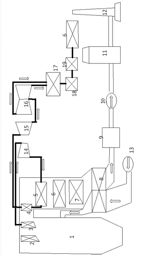
[0021] figure 1 Shown is a schematic structural diagram of a thermal power plant power generation system in the prior art. Fuel such as pulverized coal is carried into the furnace 1 by the primary air, and the air is delivered to the air preheater 8 through the blower 13 (the air is called air supply, and the air supply The wind includes secondary air, burn-off air, etc. Both the secondary air and the burn-off air enter the furnace after being heated by the air preheater (the two are at different positions at the entrance of the furnace), and are preheated in the air preheater 8 After heating, it enters the furnace 1 of the boiler. The pulverized coal in the furnace is burned up under the oxidation of the secondary air and the exhaust...


PUM


Abstract

The invention discloses a flue gas waste heat utilization system of a thermal power plant. The system comprises an air pre-heater, a first heat exchanger, an electric dust collector, a second heat exchanger, a desulfurizing tower and a chimney. The flue gas inlet and outlet of the first heat exchanger are communicated with the flue gas inlet and outlet of the electric dust collector and the flue gas inlet and outlet of the air pre-heater through pipelines respectively, the flue gas inlet and outlet of the electric dust collector are communicated with the flue gas inlet and outlet of the second heat exchanger, and the flue gas inlet and outlet of the desulfurizing tower are communicated with the chimney and the flue gas inlet and outlet of the second heat exchanger respectively; the cold source outlet and inlet of the first heat exchanger are communicated with a cold source device through pipelines; the air inlet of the second heat exchanger is communicated with the air, and the air outlet of the second heat exchanger is communicated with an air inlet of the air pre-heater through a pipeline, and the air outlet of the air pre-heater is communicated with the hearth of a thermal power plant furnace through a pipeline. The system is capable of recovering the flue gas waste heat, desulfurizing water is saved, and power consumption of an air guiding fan and electric dust collector is reduced.

Description

technical field [0001] The invention belongs to the field of thermal power plants, in particular to a waste heat utilization system for flue gas in thermal power plants. Background technique [0002] Thermal power plants use the heat generated by the combustion of fuel such as coal to heat water into steam, and the pressure of the steam drives a steam turbine to do work to generate electricity. [0003] However, in the process of thermal power generation, the flue gas released by fuel combustion contains harmful substances such as dust, carbon dioxide, sulfur oxides, nitrogen oxides, mercury and their compounds. The direct emission of flue gas not only pollutes the atmosphere, but also brings harm to people's health. It may also cause acid rain, photochemical smog, ozone hole, greenhouse effect and other phenomena, further threatening the environment for human survival. Therefore, in recent years, my country has adhered to the principles of low-carbon, clean, and high-effic...

Claims


Application Information

Patent Timeline
IPC IPC(8): F22D1/36F23L15/00
CPCY02E20/34
Inventor 赵虎军丁兆勇姜媛媛
Owner GUODIAN LONGYUAN ENERGY SAVING TECH
Why Eureka
Try Eureka