Laser-induced double-chamber micropump and fluid micropump drive method thereof

A technology of laser induction and driving method, which is applied in the field of control, micro fluid drive and supply, can solve the problems of limited service life of the pump membrane, low requirements for conveying fluid, and difficult size, so as to achieve no electromagnetic interference, simple introduction and transportation, The process is fast and the effect

Inactive Publication Date: 2015-03-04
GUANGDONG UNIV OF TECH
View PDF6 Cites 5 Cited by
  • Summary
  • Abstract
  • Description
  • Claims
  • Application Information

AI Technical Summary

Problems solved by technology

[0007] Among them, the laser shock wave drive, the sacrificial layer of the pump membrane produces a plasma explosion air mass under the laser irradiation to generate a shock wave, so the service life of the pump membrane is limited; the manufacturing process of the piezoelectric driven micropump is complex, the driving voltage is high, and the power consumption is large; the electrostatic force The drive requires a small electrode gap and a complex structure, so the production of the electrostatic micropump is very difficult, the electrostatic drive force is small, and the insulation problem between the two plates requires high processing technology; the electromagnetic drive micropump consumes a lot of energy. , large heat loss, compared with other types of micropumps, the volume is large, which is not conducive to miniaturization; bubble m

Method used


Image

  • Laser-induced double-chamber micropump and fluid micropump drive method thereof
  • Laser-induced double-chamber micropump and fluid micropump drive method thereof

Examples


Example Embodiment

[0030] Embodiments of the present invention are described in detail below.

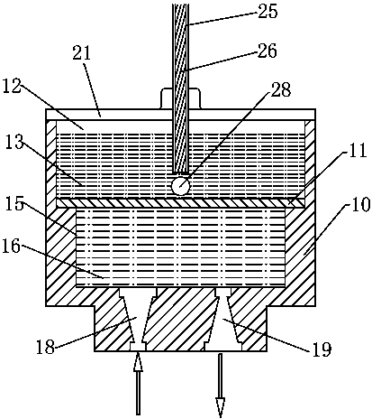
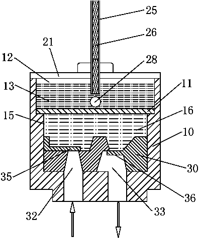
[0031] refer to figure 1 , figure 2 as shown, figure 1 demonstrated a laser-induced dual-cavity valveless micropump, figure 2 A laser-induced dual-chamber valved micropump is demonstrated. The present invention is a laser-induced double-cavity micropump, which includes a pump body 10 with an inner cavity, an elastic pump membrane 11 that is connected to the pump body 10 and separates the inner cavity into a driving cavity 12 and a pump cavity 15, and is inserted and filled with a driving liquid. The optical fiber 25 inside the driving chamber 12 of 13 is set on the pump body 10 and communicates with the pump chamber 15 to control the one-way flow control device for fluid to enter the pump chamber 15 and flow out of the pump chamber 15 in one direction. The one-way flow control device is a control structure that enables the fluid 16 to flow in one direction and is also called a directional flow c...


PUM


Abstract

The invention discloses a laser-induced double-chamber micropump. The laser-induced double-chamber micropump comprises a pump body with an inner cavity, an elastic pump diaphragm connected with the pump body and used for dividing the inner cavity into a drive cavity and a pump cavity, an optical fiber inserted into the interior of the drive cavity filled with driving liquid, and a one-way flow control device arranged on the pump body and communicated with the pump cavity to control a fluid to enter the pump cavity and flow out of the pump cavity unidirectionally. The micropump has millisecond response time, the frequency and the amplitude of the pump diaphragm can be controlled accurately, the energy utilization rate is high, wireless and remote control can be realized, the service life of the pump diaphragm is long, the type of the pumping working fluid type is not limited, and a brand new idea is provided for solving the drive problem of microfluid. The micropump can be widely applied in the fields such as a micro-injection and microfluidic control system of medicines, bioanalysis, microchemical analysis and detection, micro-electronic device cooling. The invention also discloses a fluid micropump drive method, which applies the laser-induced double-chamber micropump to drive the fluid to flow unidirectionally.

Description

technical field [0001] The invention relates to microfluid drive, supply and control technologies, in particular to a laser-induced double-cavity micropump. The present invention also relates to a fluidic micropump driving method for a laser-induced micropump. Background technique [0002] In the current medical field, the study of brain drug delivery system is of great importance to the treatment of various brain diseases such as central nervous system infection, epilepsy, brain tumor, periodic tablet headache, drug addiction, schizophrenia, stroke and convulsions. meaning. The brain drug delivery system needs to be accurate to the nanoliter and millisecond level of drug delivery requirements, therefore, a microfluidic system is required. [0003] Microfluidic system, also known as microfluidic analysis chip, micro total analysis system (μTAS) or lab on a chip, is an important branch of microelectromechanical system (MEMS). Various functional units such as microchannels,...

Claims


Application Information

Patent Timeline
IPC IPC(8): A61M5/142
CPCA61M5/142A61M2005/14208
Inventor 郭钟宁印四华陈铁牛曾柏文黄志刚杨洋杨青天罗红平
Owner GUANGDONG UNIV OF TECH
Why Eureka
Try Eureka