
Lead silicate glass used in double-clad optical fiber, and double-clad optical fiber preparation method

A technology of lead silicate glass and double-clad optical fiber, which is applied in the field of preparation of lead silicate glass for double-clad optical fiber and its double-clad optical fiber, and can solve glass tube polishing, reduce optical fiber pump coupling efficiency, and loss and other problems, to achieve the effect of shortening the preparation cycle, improving coupling efficiency, and simple process

Inactive Publication Date: 2015-03-11
SHANGHAI INST OF OPTICS & FINE MECHANICS CHINESE ACAD OF SCI
View PDF6 Cites 0 Cited by
  • Summary
  • Abstract
  • Description
  • Claims
  • Application Information

AI Technical Summary

Problems solved by technology

However, the softening point of fluoride glass and heavy metals is low, and it is difficult to weld with quartz optical fiber, so it is difficult to realize commercialization; aluminosilicate glass belongs to a kind of silicate glass, and the glass softening temperature is high, so it can be welded with quartz optical fiber, but~ 2μm poor luminous performance, difficult to achieve laser output
[0005] Multi-component glass optical fibers are generally prepared by the tube rod method, but it is difficult to polish the inner wall of the glass tube during the processing of the glass tube, which brings relatively large losses to the optical fiber; at the same time, the optical fiber inner cladding and The outer cladding is generally circular, which will generate spiral light and reduce the pump coupling efficiency of the fiber
The stacking method is a quick and easy method that can produce higher quality optical fibers (patent application number: 201310511894.6), but the patent does not cover lead silicate glass

Method used

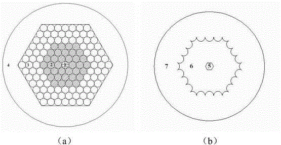
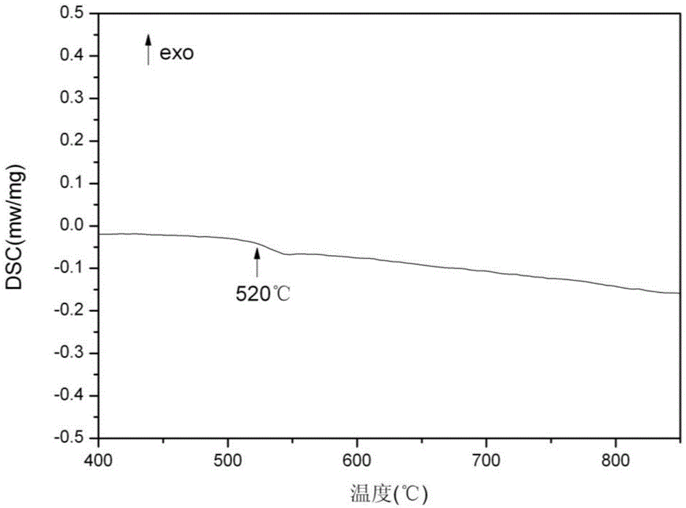
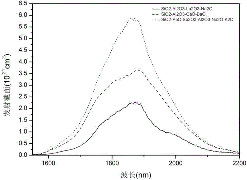

Image

  • Lead silicate glass used in double-clad optical fiber, and double-clad optical fiber preparation method
  • Lead silicate glass used in double-clad optical fiber, and double-clad optical fiber preparation method
  • Lead silicate glass used in double-clad optical fiber, and double-clad optical fiber preparation method

Examples


Embodiment 1

[0034] The preparation process of the lead silicate glass double-clad optical fiber of the present invention is as follows:

[0035] ① Preparation of core glass: Weigh the raw materials according to the formula of the core layer glass described in the invention, mix the powdery raw materials evenly, put them into a quartz ceramic crucible and melt them at a melting temperature of 1250-1350°C, and pass them into a pure Remove water by bubbling for 99.9% dry oxygen. After bubbling for two hours, clarify at 1450°C. After clarifying for half an hour, fully stir and homogenize. Send it into the annealing furnace, keep it warm for 20 hours within ten degrees above and below the glass transition temperature Tg, and then lower it to 100°C at 1-8°C / hour, then turn off the power of the annealing furnace, and naturally cool to room temperature;

[0036] ②Preparation of inner cladding glass: Except for different components, its preparation process is the same as that of core glass;

[00...

Embodiment 2

[0043] The composition of Example 2# is shown in Table 1, and the components were adjusted accordingly. The melting temperature was 1250°C, and the annealing rate was 1-8°C / hour down to 100°C. Prepare the optical fiber according to the steps ⑤-⑧ mentioned above.

Embodiment 3

[0044] The composition of Example 3# is shown in Table 1, and the components were adjusted accordingly. The melting temperature was 1300°C, and the annealing rate was 1-8°C / hour down to 100°C. Prepare the optical fiber according to the steps ⑤-⑧ mentioned above.


PUM


Abstract

The invention relates to lead silicate glass used in double-clad optical fiber, and a double-clad optical fiber preparation method. According to the invention, fiber core, inner clad and outer clad glass are prepared with a melting method; an optical fiber preform is prepared with a stacking method; and drawing is carried out, such that double-clad lead silicate glass optical fiber is obtained. As a result of laser experiment upon the drawn double-clad optical fiber, ~2mum laser output is realized under 793nmLD pump.

Description

technical field [0001] The invention relates to a double-clad optical fiber with ~2 μm laser output, in particular to a lead silicate glass for the double-clad optical fiber and a preparation method for the double-clad optical fiber. Background technique [0002] The mid-infrared laser with a wavelength of ~2μm has a very broad application prospect and important application value in military, medical, environmental protection, remote sensing monitoring, optical communication and other fields. Among them, ~2μm single-frequency lasers have attracted much attention due to their potential applications in coherent radar and as pump sources for longer-wavelength mid-infrared lasers and supercontinuum. Usually the luminescence in the ~2μm band is achieved by doping Tm 3+ ( 3 f 4 → 3 h 6 ) or Ho 3+ ( 5 I 7 → 5 I 8 ) to obtain. From the material point of view, the gain fiber used for ~2μm fiber laser can be divided into silica fiber and multi-component glass fiber. [000...

Claims


Application Information

Patent Timeline
IPC IPC(8): C03C13/04
CPCC03C13/046C03C3/105C03C4/12C03C13/04C03B37/01208C03B37/02763C03B2201/36C03B2201/50C03B2203/23
Inventor 刘雪强陈丹平王龙飞李文涛关珮雯
Owner SHANGHAI INST OF OPTICS & FINE MECHANICS CHINESE ACAD OF SCI
Learn More