
Direct separation method of silicon tetrafluoride and anhydrous hydrogen fluoride mixed gas

A technology of silicon tetrafluoride and mixed gas, applied in the direction of fluorine/hydrogen fluoride, silicon halide compound, hydrogen fluoride, etc., can solve the problem of difficult separation of silicon tetrafluoride and hydrogen fluoride gas, no replacement of silicon tetrafluoride, no description of the product Purity and other issues, to achieve the effect of convenient equipment selection, reduce heat load, and reduce energy consumption

Active Publication Date: 2015-06-03
YUNNAN TIANAN CHEM CO LTD +1
View PDF3 Cites 5 Cited by
  • Summary
  • Abstract
  • Description
  • Claims
  • Application Information

AI Technical Summary

Problems solved by technology

The disadvantages of this process are: (1) It is difficult to separate silicon tetrafluoride and hydrogen fluoride gas only by controlling the reaction temperature; (2) the specific process of obtaining silicon tetrafluoride gas and hydrogen fluoride gas is not explained; (3) there is no State the specific product purity
The disadvantages of this process are: (1) Silicon tetrafluoride gas is sent to the rectification tower for separation together with the hydrogen fluoride liquid, which brings certain difficulties to the rectification operation; (2) The temperature of the top condenser is -80~-70 °C, the energy consumption is large, the cost is high, and it is not suitable for further expansion of the scale; (3) the extraction of silicon tetrafluoride in the liquid phase will lead to serious entrainment of hydrogen fluoride, resulting in the loss of hydrogen fluoride products; (4) a large amount of concentrated sulfuric acid treatment is required The moisture in the mixed gas and the moisture and hydrogen fluoride in the silicon tetrafluoride will produce a large amount of dilute sulfuric acid. Considering the utilization or concentration of dilute sulfuric acid requires a lot of energy consumption

Method used


Image

  • Direct separation method of silicon tetrafluoride and anhydrous hydrogen fluoride mixed gas

Examples


Embodiment 1

[0036] Follow the steps below to separate silicon tetrafluoride and anhydrous hydrogen fluoride mixed gas:

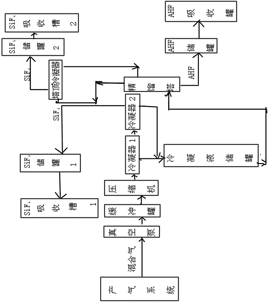
[0037] a. Control the vacuum degree of hydrogen fluoride and silicon tetrafluoride output system by vacuum pump to -0.02MPa, adjust the outlet exhaust pressure of vacuum pump to 0.13MPa, and pump the mixed gas of hydrogen fluoride and silicon tetrafluoride to a buffer tank of 0.5 cubic meters for collection . The gas is compressed to 0.5Mpa by the compressor. After compression, the gas temperature is about 90°C and enters the condenser 1. After cooling to 40~45°C, most of the hydrogen fluoride gas is liquefied, and the silicon tetrafluoride remains in the gas phase.

[0038]b. The liquid phase in step a enters the condensate storage tank, the gas phase enters the condenser 2 and continues cooling to -25°C with ethylene glycol-water solution, the residual hydrogen fluoride gas is condensed again, and enters the condensate storage tank, and the gas phase obtains a purity ...

Embodiment 2

[0041] a. Control the vacuum degree of hydrogen fluoride and silicon tetrafluoride output system by vacuum pump to -0.02MPa, adjust the outlet exhaust pressure of vacuum pump to 0.13MPa, and pump the mixed gas of hydrogen fluoride and silicon tetrafluoride to a buffer tank of 0.5 cubic meters for collection . Then the gas is compressed to 0.6MPa by the compressor and enters the condenser 1. After compression, the gas temperature is about 90°C. After cooling to 40-45°C, most of the hydrogen fluoride gas is liquefied, and the silicon tetrafluoride remains in the gas phase.

[0042] b. The liquid phase in step a enters the condensate storage tank, the gas phase enters the condenser 2 and continues cooling to -25°C with ethylene glycol-water solution, the residual hydrogen fluoride gas is condensed again, and enters the condensate storage tank, and the gas phase obtains a purity ≥ 99.0wt% silicon tetrafluoride gas product is sent to silicon tetrafluoride storage tank 1 for storage...

Embodiment 3

[0045] a. Control the vacuum degree of hydrogen fluoride and silicon tetrafluoride output system by vacuum pump to -0.02MPa, adjust the outlet exhaust pressure of vacuum pump to 0.13MPa, and pump the mixed gas of hydrogen fluoride and silicon tetrafluoride to a buffer tank of 0.5 cubic meters for collection . Then the gas is compressed to 0.7MPa by the compressor. After compression, the gas temperature is about 90°C and enters the condenser 1. After cooling to 40~45°C, most of the hydrogen fluoride gas is liquefied, and the silicon tetrafluoride remains in the gas phase.

[0046] b. The liquid phase in step a enters the condensate storage tank, and the gas phase enters the condenser 2 and continues cooling to -20°C with ethylene glycol-water solution to condense the residual hydrogen fluoride gas again, and enters the condensate storage tank, and the gas phase obtains purity ≥99.0wt% silicon tetrafluoride gas product, and sent to silicon tetrafluoride storage tank 1 for storag...


PUM


Abstract

The invention relates to the technical field of fluorine chemical industry, and in particular relates to a direct separation method of a silicon tetrafluoride and anhydrous hydrogen fluoride mixed gas. The method comprises the following process steps: a, collecting a silicon tetrafluoride and hydrogen fluoride mixed gas, which is obtained by pyrolysis of fluosilicic acid, compressing through a compressor, entering a condenser 1, cooling, and entering obtained liquefied hydrogen fluoride to a condensate storage tank; b, feeding the cooled silicon tetrafluoride gas to a condenser 2, further cooling with an ethylene glycol-water solution, removing residual hydrogen fluoride to obtain a silicon tetrafluoride gas and entering a silicon tetrafluoride storage tank 1 to store; and c, carrying out rectification and purification on liquid phases in the step a and the step b, and controlling the operation pressure and the overhead condensation temperature of a rectifying tower to obtain the refined liquid hydrogen fluoride product. The method has the advantages of being feasible to operate, low in investment, low in energy consumption, and free of difficult-to-treat waste, and is an economical, efficient and environment-friendly separation method; and equipment is not corroded.

Description

technical field [0001] The invention relates to the technical field of fluorine chemical industry, in particular to a method for directly separating the mixed gas of silicon tetrafluoride and anhydrous hydrogen fluoride. Background technique [0002] Hydrogen fluoride is a raw material for the production of refrigerant "Freon", fluorine-containing resin, organic fluoride and fluorine. In chemical production, it can be used as a catalyst for organic synthesis such as alkylation, polymerization, condensation, and isomerization. It is also used to corrode the formation when mining certain deposits, and to extract rare earth elements and radioactive elements. In the atomic energy industry and nuclear weapon production, it is the raw material for the manufacture of uranium hexafluoride, as well as the raw material for the production of rocket fuel and additives. It can also be used to corrode glass and impregnate wood. Anhydrous hydrogen fluoride (hydrogen fluoride) has a boili...

Claims


Application Information

Patent Timeline
Patent Type & Authority Applications(China)
IPC IPC(8): C01B7/19C01B33/107
CPCC01B7/193C01B7/196C01B33/10705
Inventor 黄天江刘强张宗凡杨胜军李国鹏李玉叶李侠
Owner YUNNAN TIANAN CHEM CO LTD
Learn More