Steel-aluminum composite hydraulic prop and manufacturing method and device thereof

A hydraulic prop, steel-aluminum composite technology, used in mining equipment, props/supports, earth-moving drilling, etc., can solve the difficulty in realizing the metallurgical combination of hydraulic prop core blank and stainless steel sleeve, and poor surface wear resistance and impact resistance. , difficulty in large-scale production, etc., to achieve the effects of controllable composition and thickness of the deposited layer, low overall density, and improved tensile strength

Inactive Publication Date: 2015-06-17
JIANGSU SHUNDA MACHINERY EQUIP
View PDF6 Cites 2 Cited by
  • Summary
  • Abstract
  • Description
  • Claims
  • Application Information

AI Technical Summary

Problems solved by technology

In order to alleviate the serious surface corrosion caused by the harsh working environment, surface coating is often treated by coating, but the surface has poor wear resistance and impact resistance, and serious environmental pollution; the recently developed laser surface melting Laying technology can solve the wear resistance and impact resistance of the hydraulic prop surface to a certain extent, but due to the complex process, low production efficiency and high cost, it is difficult to form large-scale production; in addition, there is also the method of using stainless steel sleeves, It is expected to reduce the production cost while improving the corrosion resistance, wear resistance and impact resistance of the hydraulic prop. However, it is difficult to realize the metallurgical bond between the hydraulic prop core blank and the stainless steel sleeve by using this simple machining method. The surface layer is prone to detachment and the service life is short

Method used


Image

  • Steel-aluminum composite hydraulic prop and manufacturing method and device thereof

Examples


Embodiment 1

[0027] Example 1 Manufacturing equipment of steel-aluminum composite hydraulic prop

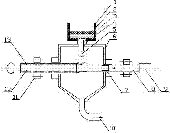
[0028] Such as figure 1 As shown, the manufacturing equipment of steel-aluminum composite hydraulic prop includes medium frequency induction furnace 1, catheter tube 3, atomizer 4, deposition chamber 6, fixture 7, ejector rod 8, ejector device 9, exhaust port 10, rotary Driving roller 11, aluminum alloy pillar core blank 12 and stainless steel deposition layer 13. The stainless steel material is melted in the intermediate frequency induction furnace 1 to form a stainless steel melt 2, and the stainless steel melt 2 is introduced into the atomizer 4 through the catheter 3, and the high-pressure nitrogen atomizes the stainless steel melt through the atomizer 4 to form a jet stream 5 .

[0029] Below the intermediate frequency induction furnace 1 is provided with a deposition chamber 6, and at the bottom of the intermediate frequency induction furnace 1 is provided with a liquid conduit 3 for ...

Embodiment 2

[0033] Example 2 Manufacture of Steel-Aluminum Composite Hydraulic Prop

[0034] The 7075 aluminum alloy prepared by extrusion casting was used as the pillar core billet, and the 304 stainless steel was used as the cladding material. The composite core billet experiment of the cladding layer was carried out by spray deposition. use figure 1 The steel-aluminum composite hydraulic prop manufacturing equipment shown is tested, and the experimental steps are as follows:

[0035] 1) Using a 100kW intermediate frequency induction melting furnace, first add 36kg of electrical pure iron block material to the furnace 1 of the magnesia furnace lining, turn on the intermediate frequency furnace, gradually increase the power to 85kW, and keep the frequency at about 2500Hz for melting. After the iron block is completely melted, add 4.5Kg Ni block, add 9Kg Cr block after melting, then add 1Kg Mo60%-Fe alloy to obtain 304 stainless steel melt 2, keep power about 90 kW, when the melt tempera...

Embodiment 3

[0040] Example 3 Manufacture of Steel-Aluminum Composite Hollow Pillars

[0041] Using 7075 aluminum alloy extruded 100×30 (outer diameter 100mm, wall thickness 30mm) tube billet as pillar core billet, 304 stainless steel as cladding material, spray deposition was used to carry out cladding layer composite core billet experiment. use figure 1 The steel-aluminum composite hydraulic prop manufacturing equipment shown is tested, and the experimental steps are as follows:

[0042] 1) Use a 100kW intermediate frequency induction melting furnace, add 50kg304 stainless steel rods, and the melting power is about 90kW. When the melt temperature is about 1550°C, add 50g of ferromanganese and 75g of ferrosilicon to conduct deoxidation and refining treatment on the stainless steel melt 2, and adjust the intermediate frequency The power of the furnace is about 100kW, so that the temperature of the stainless steel melt reaches 1600°C;

[0043] 2) Put the 100×30 (outer diameter 100mm, wall...


PUM


Abstract

The invention discloses a method for manufacturing a steel-aluminum composite hydraulic prop and belongs to the technical field of hydraulic props. The method comprises the steps of 1, smelting a spraying layer material; 2, conducting core blank surface pretreatment; 3, conducting spray deposition; 4, obtaining a sample. The invention further discloses a device for manufacturing a steel-aluminum composite hydraulic prop. The device comprises a medium-frequency induction furnace, wherein a deposition chamber is arranged below the medium-frequency induction furnace, a liquid guiding pipe communicated with the deposition chamber is arranged on the bottom of the medium-frequency induction furnace and located in an atomizer, and the atomizer is arranged between the medium-frequency induction furnace and the deposition chamber. The invention further discloses a steel-aluminum composite hydraulic prop manufactured with the method and device. The steel-aluminum composite hydraulic prop has the advantages of being low in overall density, high in specific strength, resistant to shock and high in abrasion resistance and corrosion resistance. The device for manufacturing the steel-aluminum composite hydraulic prop is simple in structure and easy to use and popularize. The method for manufacturing the steel-aluminum composite hydraulic prop is simple.

Description

technical field [0001] The invention belongs to the technical field of hydraulic props, in particular to a steel-aluminum composite hydraulic prop and its manufacturing method and [0002] Manufacturing Equipment. Background technique [0003] The hydraulic prop is used for underground safety support in coal mines. It has become an indispensable product for fully mechanized mining accessories in the modern coal mine industry. With the general coal mining gradually developing towards safe and mechanized coal mining, the single hydraulic prop demand will increase day by day. [0004] However, due to the harsh working conditions of the hydraulic prop, severe corrosion, and various wear (corrosion wear, abrasive wear, fatigue wear), its life is short, and the general life span in some mines with poor water quality is only a few months. At present, the hydraulic prop is made of hot-rolled seamless steel pipe, the commonly used material is 27SiMn steel, and then assembled after ...

Claims


Application Information

Patent Timeline
Patent Type & Authority Applications(China)
IPC IPC(8): B22D17/00B22D19/16E21D15/44
Inventor 陈刚苏峰
Owner JIANGSU SHUNDA MACHINERY EQUIP
Why Eureka
Try Eureka